meta data for this page
Controller (v.0.8.13)
The controller allows you to control BLDC (Brushless Direct Current Motor) and PMSM (Permanent Magnet Synchronous Motor) electric motors. At the moment we are producing three types of controllers for different motors power.
Technical specifications of controllers:
| Parameters | Controller 6F v.2 | Controller 12F | Controller P24F |
|---|---|---|---|
| Maximum power | 4 000W | 12 000W | 27 000W |
| Nominal power | 2 000W | 5 000W | 10 000W |
| Voltage range | 30-90V | ||
| Phase current, max | 120A | 250А | 500А |
| Battery current, max | 90A | 150A | 350A |
| Supply out | 12В 3A | ||
| Operating temperature range | -30°C до 80°C | ||
| Phase wires | 11AWG 5mm bullets | 8AWG XT150 | No wires, M6 terminals |
| Battery wires | 12AWG XT60 | 10AWG XT90 | No wires, M6 terminals |
| Hall connectors | 2.8mm 6P auto or Juliet waterproof | JWPF 8P connector (Hall/Encoder) | |
| Wires length | 140 mm | 190 mm | No wires |
| Control modes | Square, sensorless, FOC, charger, MPPT | ||
| Protection | Temperature, hardware overcurrent protection, IO ports overvoltage protection for P24F | ||
| Protection class | IP57 (IP67 with compound) | IP67 (compound filled) | |
| Size, without wires | 53х32х91 mm | 86х43х125 mm | 205х98х50 mm |
| Weight | 280g (with compound 430g) | 640g (with compound 890g) | 1440g (compound filled) |
| Warranty | 2 years (with compound potting — 3 year) | 3 year | |
In the kit:
- CAN-cable 1,2-meters length for connection to the On-board Computer.
- Phase wires.
- Battery wires
- Hall sensors wire.
Phase, battery, and Hall sensors wires are supplied with connectors, depending on the type and specification of the controller in the order.
Optionally you can order:
- САN-cables 0,3 and 2 meters length.
- Controller-side inputs for connection throttle, brakes levers directly to the Controller.
- PWM/PAS wire for connection PAS, fans for cooling or brake lights.
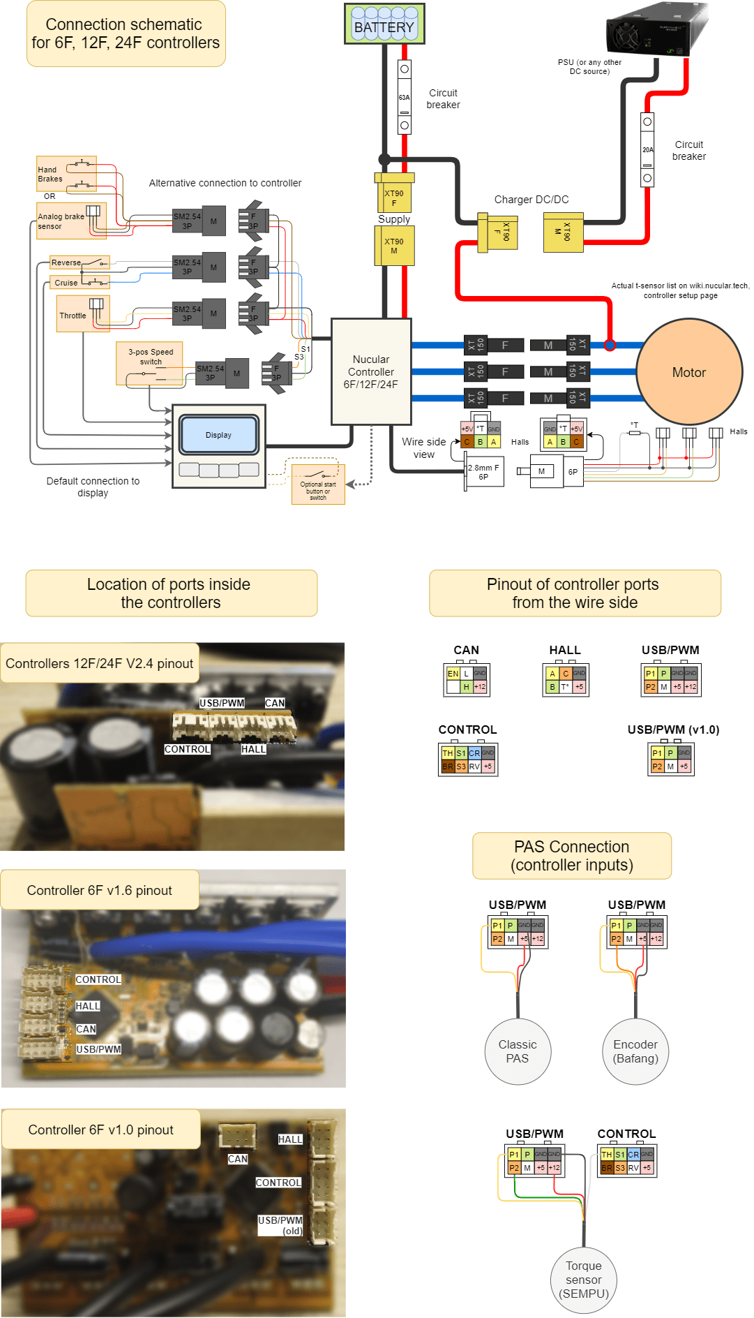
Connection diagram
First, connect the three phases of the electric motor. It does not matter in which order and by which color you connect the phases, the controller will automatically detect them during auto-setup. Next, connect the hall connector as shown in the diagram below. You also need to connect the throttle lever and battery power. We also recommend connecting the brake levers, as their actuation turns off the motor. A simple rule — in any incomprehensible situation, press the brake.
When the power is turned on for the first time, the controller will start automatically. To enable/disable the controller, you must connect an external switch according to the diagram or configure the button located on the back of the On-board computer in the menu Devices > Controller > Extra parameters > Disable button.
You can find the wiring diagrams for 6F,12F,24F, On-board computer and uLigt on this link, wiring diagram for P24F and Encoder board here. By default, all peripherals (throttle, brake, switches, etc.) are connected into ports located on the backside of On-board computer . To access the ports, you need to unscrew five screws and remove the plastic cover. For connection, use PHD 2.0 connectors and crimp pins, which are included in the kit. If you do not have a crimping tool such as Crimper SN-2549, you must order “Crimped wires for display”. The On-board computer is connected to the controller with one CAN-wire 1.2 meters long, which is included in the controller kit. Be careful, the CAN-wire from the Controller is connected to the SYSTEM connector on the backside of the On-board computer.
If you want to connect peripherals directly to the Controller, you need to order “Control-side inputs”, in the diagram below this switching option is designated as “Alternative connection”. You can also use a mixed connection, for example, connect the throttle lever to the On-board computer, and the brake lever to the Controller.
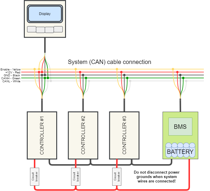
Connecting multiple controllers
If you want to connect two or more Controllers, you can use a CAN splitter with four ports (purchased separately) or a lighting controller uLight, which also has three own CAN ports. The On-board computer supports the connection of up to eight Controllers.
For example, for a two-motor connection scheme, which is used on all-wheel-drive electric scooters, in addition to the second controller, you will need a CAN-splitter and one more CAN wire (there are 2, 1.2, and 0.3 meters long). Each Controller has a standard CAN-wire 1.2 m long. These wires from both controllers must be connected to a CAN-splitter, and from it one CAN-wire connects directly to the On-board computer. In the On-board computer, you can configure both controllers are separate.
Pay attention to the connection diagram. Do not disconnect power grounds when system wires are connected! First connect all power wires and only then CAN wires. When disconnecting the controllers, first disconnect all CAN wires and only then disconnect the power cables; it is also recommended to discharge the controller capacitors with a resistor or an ordinary light bulb.
How to start?
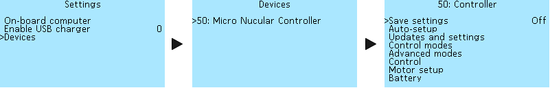
After you have connected the Controller and Controls according to the diagram, you need to configure the battery parameters. For this, go to the Settings > Devices section, select the Controller in the list of devices, then go to the Controller > Battery section and specify the supply voltage range. For a detailed description, see the section Battery.
After configuring the battery, you need to run Auto-setup in the Controller > Auto-setup menu section. Ensure that the phase and battery wires are well contacted and insulated before running auto-setup. Check that the Hall sensor wire connectors are fully inserted into the mating parts. For details, see the section Auto-setup. After auto-setup, you need to adjust the speedometer to display the speed correctly, see the section Speedometer setup.
Menu navigation
Use the On-board computer buttons to navigate through the menus. Left button — return to the previous menu or cancel editing. Right button — go to the menu section and confirm the parameter selection. The two middle buttons — to move up/down through the menu and select the value of the menu item.
Settings saving
In the menu item Controller > Save settings you can save all the settings made. Press the right button of the Onboard-computer and select On to save. If you do not save the settings, they will be reset after restart.
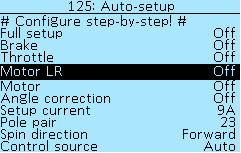
Auto-setup
The auto-setup function in the Controller > Auto-setup menu section allows you to automatically set up the electric motor, throttle, and brake levers. If the throttle and brake levers are connected to the On-board computer, then they must be configured in section menu On-board computer > Control setup. In this case, when starting the function Full setup, you must skip the menu items Brake and Throttle (they will be detected as an error anyway) or you can not start Full setup and activate each setup menu item manually starting with Motor LR, then Motor and Angle correction. If you have an electric motor without a temperature sensor, then you need to disable it in menu section Controller > Motor setup > Motor t°-sensor > Sensor type. If this is not done, then auto-setup of the motor will show an error (Timeout).
The auto-setup menu starts the subprogram and shows only the process. All settings are saved under Controller > Motor setup. After restarting the Controller, all switches will be in the Off position.
Once you have specified the battery supply voltage in the Controller > Battery section, you can proceed to calibrate the motor and levers in the Auto-setup section.
Before auto-setup the angles, we recommend specifying the correct number of motor pole pairs in menu item Controller > Auto-setup > Pole pairs. See Motor informationfor this number for the most popular motors. If your motor is not on the list, check with the manufacturer or search the Internet for information.
Be careful! Before running autotuning, check that the drive wheels of your e-bike are not touching the surface and that the pedals (if equipped) do not touch anything when spinning. When adjusting the Hall sensors, the motor rotates in both directions, be careful and do not stand near the bicycle pedals. The motor will rotate five times, once when the motor is detected and four times when correcting the angle.
If you have a throttle lever and an analog brake connected, then you need to enable Full Setup, and follow the instructions on the On-Board computer screen. The corresponding menu items will indicate when to press and release the throttle or brake lever.
If only one throttle lever is connected, you must independently turn on the items step-by-step: Throttle, Motor LR, Motor, Angle correction. When you enable each of the menu items, the hints will be displayed. Auto-setup function Motor LR detects the inductance and resistance of the motor. You can see the measurement results in the menu section Controller > Motor setup, items Phase resistance, Inductance d and Inductance q.
If the motor is heavy and autodetect does not happen, you can gently push it with your hand or increase the tuning current in the Controller > Auto-setup > Setup current section, for example, twice. The setup current can be selected in the range from 2A to 50A, in increments of 1A.
If the motor is rotating in the wrong direction, go to Controller > Auto-setup > Spin direction and change the direction of rotation. You can choose from two options Forward or Invert. A similar setting is available in the Controller > Motor setup> Spin direction menu. It doesn't matter in which menu you make the setting, after saving, the direction of rotation will be reversed in both sections.
If an error occurs during autotuning, see the section Diagnostics of controller malfunctions. In the menu item Controller > Auto-setup > Control source you can select the sources of control for the Controller. See Control Source section below for details.
Firmware update
In the menu section Controller > Update and Settings, you can update the Controller's firmware, reset settings, import or export a configuration. You can upload all controller settings to a microSD card. The created file with the name NCconf.cfg - NCconf9.cfg you can open with the “Notepad” program, see all your settings, make any changes, save. Likewise, you can import a previously saved configuration into the Controller. Trip computer settings cannot be exported or imported. On-board computer settings can be exported and imported in separate sections of the Onboard computer menu. This function is only available in the On-board computer firmware version 0.7B and higher.
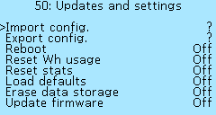
Import config. — loads the settings from the file NCconf.cfg - NCconf9.cfg up to a maximum of 9 different configurations, choosing a file number from 1 to 9. After a successful import, error messages may appear in the message, this means that not all the settings have been imported. In this case, it is advisable to check the downloaded settings with the original file by opening it in Notepad.
Export config. - saves the settings to the NCconf.cfg - NCconf9.cfg file up to a maximum of 9 different configurations, choosing a file number from 1 to 9.
Reboot — restarts the device. If the settings have not been saved, they will be reset.
Reset Wh usage — resets the accumulated number of Watt-Hours in the controller. This indicator is displayed in the statistics of the On-board computer, see section Statistics.
Reset stats — resets mileage in kilometers.
Load defaults — after a reset, the default settings are loaded but not saved. If you restart the Controller without saving after a reset, the previous settings will be loaded.
Erase data storage — This function may be needed for the correct firmware update, rollback to default settings, in a situation where user actions lead to incorrect operation of the Controller. If the controller has stopped saving the settings, do a reset, wait 3 seconds, and try to save again.
Update firmware — starting the firmware update process. You can download the current firmware version and read the rules of update in the Firmwaresection. To update, download the firmware file to the root directory of the microSD card with the Fat/Fat32 file system. Insert the card with the contacts facing up into the slot on the On-Board Computer and select On . When the update process is complete, a message appears on the screen Update finished. Press the left button and check the update version under Controller > Device Information.
Control modes
In the menu section Controller > Control modes you can configure and save three presets of the parameters of the electric motor and switch between them using a 3-position switch or buttons on the On-board computer. The currently active mode number is displayed at the top of the main screen. After setting, it is necessary to activate the modes in the menu item Controller > Additional modes > Enable additional modes by setting the value On. In the same menu Controller > Additional modes you can make detailed settings for each mode (see the section Additional modes).
If there is no speed switch, then mode 1 is the default. If the switch is connected to the On-board computer, it is necessary to configure the On-board computer buttons in the On-board computer > Button settings menu. See section Buttons setup.
Modes setup
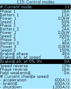
The # Current mode line displays the currently selected control mode. List of possible options:
N — neutral.
S1 — speed 1.
S2 — speed 2.
S3 — speed 3.
RV — reverse.
Four parameters are used to configure each mode:
Phase — the maximum value of the phase current, in Amperes (A). Select of values from 0A to 500A, in increments of 2A. When setting, consider the maximum phase current of your controller type. In most cases, we recommend specifying the value of the phase current 1.5-2 times higher than the battery current.
Battery — the maximum value of the battery current, in Amperes (A). Select of values from 2A to 400A, in increments of 2A. When setting up, consider the capabilities of the connected battery and the maximum battery current of your controller type.
Power — maximum power (discharge) of the battery, in kilowatts (kW). Select of values from 0.00kW to 30.0kW, in increments of 0.1kW. Set to 0.0kW to disable the power limiting limit.
Speed — maximum speed in percentage (%). Select of values from 4% to 150%, in increments of 2%. The value of this parameter determines the percentage of speed depending on the reference speed (see section Speedometer setup). A speed value over 100% activates the field weakening mode, which allows the motor to accelerate above the supply voltage (see section Field weakening setup).
Electric brake setup
Braking phase — the value of the phase current of braking by the motor, in Amperes (A). Select of values from 0A to 500A, in increments of 2A. For braking to zero, it is recommended to enable Active braking in the section Controller > Control. When using limit switches on mechanical brakes, lower brake current change speed makes recuperation more smooth.
Braking phase at speed control
Braking ph. at speed — phase braking current during speed control, in Amperes (A). Select of values from 0A to 500A, in increments of 2A. This function allows you to slow down when you reset the throttle stick. Works only with Direct Drive motors, without a clutch.
Also to use this mode should be selected: Speed or Speed and Torque mode in the Controller > Control > Throttle Mode menu item. In the menu item Controller > Control > Speed lim. at 0% throttle enable the speed limit at 0% throttle (optional), enable if you need braking with completely released throttle.
Regenerative braking setting
Braking ph. at 0% throttle — phase braking current with the throttle handle released, in Amperes (A). Select of values from 0A to 500A, in increments of 2A. This function allows regenerative braking to be initiated when the throttle is released.
This function will be active if additional modes are disabled in the Controller > Advanced modes menu section or if, with activated additional modes, in one of the menu sections Mode S1, Mode S2 or Mode S3 in menu item Braking ph. at 0% throttle was setup is 0A.
Reverse setup
Speed reverse — reverse speed, in percentage (%). Select of values from 2% to 150% , in increments of 2% . The value of this parameter determines the percentage of speed depending on the reference speed (see section Speedometer setup). A speed value over 100% activates the field weakening mode, which allows the motor to accelerate above the supply voltage (see section Field weakening setup).
Phase reverse — the value of the reverse phase current, in Amperes (A). Select of values from 10A to 500A, in increments of 2A.
Field weakening setup
Field weakening — the magnitude of the field weakening current, in Amperes (A). Select of values from 0A to 500A, in increments of 2A. This setting allows you to increase the maximum motor speed and depends on the supply voltage, in any case, the speed will be no more than the maximum supply voltage (Vmax) of the controller (95V limit).
The current of weakening creates a field that acts against the field of the permanent magnets. The superposition of these fields creates an equivalent field that is below nominal. The attenuation efficiency depends on the parameters of the motor. The best results can be obtained with IPM motors.
Warning! High Field weakening setting may damage your motor! It is not recommend to exceed 500Hz on a rotor for most 0.35mm steel motors
To set up the weakening, you need:
- for one of the control modes in the section Controller > Control modes specify a speed value greater than 100%, for example, Speed 3 is 120%.
- set the weakening current value in the section Controller > Control modes, you can start from 30A.
Field weakening is activated when the maximum speed is reached, the Controller adds weakening current, limiting the phase current and weakening current specified in the control mode. That is if the effective phase current is 70A, and the weakening current is set to 30A, then a minimum of 100A must be specified in the phase current settings. If the phase current increases to 80A, then only 20A will remain for weakening because 80A 20A = 100A.
Also, the Controller will limit the speed of rotation of the motor so that its effective EMF does not exceed the maximum supply voltage of the controller (not the battery). If the motor starts twitching on the suspended wheel, then it is necessary to reduce the weakening current.
Current change speed
# Current change speed.
- acceleration, select of values from 50A/s to 50000A/s, in increments of 100A/s.
- braking, select of values from 50A/s to 50000A/s, in increments of 100A/s.
- shutdown, select of values from 50A/s to 50000A/s, in increments of 100A/s.
Three parameters determine the rate of change of the current (smoothness). The higher the value, the faster the current build-up in the motor will occur. For conventional brake levers, it will be useful to reduce the parameter braking for a smoother activation of the regeneration. If the throttle response seems too slow, you need to increase the parameter acceleration. The parameter shutdown determines how quickly the current drops after throttle and brakes are released.
Advanced control modes
In the menu section Controller > Advanced modes enables the control modes and activates the advanced settings for each of these modes.
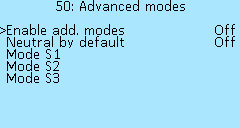
To activate the control modes, select Controller > Advanced modes > Enable add. modes and to set On.
In the menu Controller > Advanced modes > Neutral by default you can activate the neutral mode (N) when the controller starts up, which will be active until one of the speed modes is activated. In neutral mode, only the electric brake operates, throttle and PAS are disabled. This mode is recommended for use with speed buttons (not a switch). The function does not work with a 3-position switch (functions of the S1of3 and S3of3 ports in the Controller > I/O configuration menu).
Neutral timer — switches neutral on after a certain time in seconds (s), which is set in the settings. To turn it off, switch the speed mode.
Each mode has its own section in the Controller > Advanced modes > Mode S1, Mode S2, Mode S3 with the following settings:
 Throttle mode — selection of the operating mode of the throttle lever, read more in the section Throttle control mode setup.
Acceleration lim. and Deceleration lim. — are specified in ERPM/s, select of values from 0 ERPM/s to 500000 ERPM/s, in increments of 200 ERPM/s . These settings allow you to limit the speed of acceleration or deceleration of the motor, it is convenient to use on slippery surfaces. For setting go to the Controller > Status flags section, in this menu there are two parameters that register the maximum acceleration and deceleration — Max acceleration and Max deceleration. Reset the values of these parameters in the same section of the menu, then you need to ride your e-bike in order to register the current dynamics of acceleration and deceleration. You can use these values as a reference and decrease them if you need to limit change speed. If the type of surface changes, for example, it becomes too slippery, then these values can be reduced until it becomes comfortable to catch the moment when the wheel loses traction.
Braking phase — the value of the phase current of braking by the motor, in Amperes (A). Select of values from 0A to 500A, in increments of 2A. For braking to zero, it is recommended to enable Active braking in the section Controller > Control. When using limit switches on mechanical brakes, lower brake current change speed makes recuperation more smooth.
Braking ph. at 0% throttle — phase braking current with the throttle handle released, in Amperes (A). Select of values from 0A to 500A, in increments of 2A. This function allows regenerative braking to be initiated when the throttle is released. If 0A is specified or additional modes are disabled in the Controller > Advanced modes section of the menu, then for the recuperation level will be used value from menu item in the Controller > Control modes > Braking ph. at 0% throttle menu item.
Revers — reverse gear activation when the control mode is selected. Select of values On or Off.
Cruise — activation of the cruise function. Select of values On or Off. Convenient to use with cruise mode Allow Throttle hold in the menu section Controller > Control > Cruise > Cruise to enable cruise in certain modes. See section Cruise control setup.
Disable motor — completely disables motor control. Select of values On or Off.
Disable throttle — disable throttle control. Select of values On or Off.
Active braking — allow the brake to use the battery for stopping. Select of values On or Off.
Reverse on brake — after stopping, pressing the brake lever again activates reverse speed. Select of values On or Off.
Speed lim. at 0% throttle — allows limiting the speed when the throttle lever is released. Select of values On or Off. Selecting Off disables motor control when the throttle is released.
Disable PAS — disables the Pedal Assist. Select of values On or Off.
PAS Scale — extra PAS multiplier for tuning, decreases PAS signal for smoother control on high power modes. Select of values from 1% to 100%, in increments of 1%.
Control
In the Controller > Control menu section you can setup setting the engine controls, throttle levers, torque and PAS sensors, cruise control.
PAS and Torque sensor setup
In the menu section Controller > Control > Pedal Assist System you can set up the Pedal Assist System (PAS), which connects the electric motor when pedaling.
To be able to connect the PAS system, it is necessary to order the PWM IO/PAS cable as an option. The PAS system connects to the Controller via the PWM IO/PAS wire to the P1/P2 or IO5/IO6 ports of the USB/PWM connector. When using a SEMPU pressure sensor, an additional signal output from the TH port of the connector Control is required. Note: to use P1/P2 or IO5/IO6 ports, setup them to Spec. mode in IO Configuration.
You can look at the connecting methods of various PAS systems at Connection diagram.
The PAS, unlike the Torque sensor, controls the throttle by frequency and not by the force of rotation. The PAS setup menu consists of the following items:
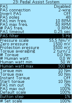
PAS — selection of pedaling assistant type PAS sensor or Torque sensor. If there is no PAS system, select Disabled.
PAS connection — 1-wire or 2-wire connection option, two wires are used for the angle sensor (encoder).
Invert PAS — change of direction in case of 2-wire connection. Select of values On or Off.
PAS poles — number of impulses per pedal revolution. Select of values from 1 to 200, in increments of 1.
PAS min. freq. — the minimum pedal speed (cadence) at which the motor starts, RPM. Select of values from 1 RPM to 500 RPM, in increments of 1 RPM.
PAS max freq. — the maximum pedal speed (cadence) at which the motor starts, RPM. Select of values from 10 RPM to 1000 RPM, in increments of 5 RPM.
# PAS freq. — the value of the signal coming from the PAS in real-time.
PAS timeout — the time after which the motor turns off after stopping pedaling, in seconds (s). Select of values from 0.02s to 5.00s, in increments of 0.02s.
PAS filter — smoothing the control signal for smoother operation, in hertz (Hz). Select of values from 1 Hz to 100 Hz, in increments of 1 Hz.
PAS min out — minimum control level when PAS is running, in percent (%). Select value from 0% to 100%, in increments of 1%.
PAS max out — maximum control level, in percent (%). Select of values from 0% to 100%, in increments of 1%. By analogy with the “pressed” throttle, PAS sends a signal within the specified limits.
Further in the menu are the settings related to the pressure sensor (Torque sensor).
Pressure scale — in Newton-meters/volts (Nm/V). You can calibrate by placing a load on the pedal and calculating the torque on the shaft through the lever. Select value from 0.0 Nm/V to 100.0 Nm/V, in increments of 0.5 Nm/V.
Zero pressure — zero pressure, in millivolts (mV). Select of values from 0mV to 10000mV, in increments of 10mV.
Protection pressure — switching off the pressure sensor when the threshold of the specified value is exceeded, in millivolts (mV). Select of values from 0mV to 10000mV, in increments of 100mV.
Torque averaging — period for which is torque value updated. Measured in half turns (turn/2). If the torque sensor measures only one pedal, then the period must be a multiple of two. Select of values from 1 turn/2 to 20 turn/2, in increments of 1 turn/2.
# Torque — shows the current torque at the sensor, in Newton meters (Nm).
# Human watt — shows the average power you develop when pedaling, in watts (W).
Human watt min — the minimum power you develop to activate the motor, in watts (W). Select of values from 0 W to 500 W, in increments of 10 W.
Human watt max — the maximum power for 100% activation, in watts (W). Select of values from 0 W to 1000 W, in increments of 10 W.
Torque min — the torque at which the throttle signal starts to increase, Newton-meters (Nm). Select of values from 0 Nm to 100 Nm, in increments of 2 Nm. All values less than this level is 0% of throttle.
Torque max — the torque, which limits the level of 100% throttle, Newton-meters (Nm). Select of values from 0 Nm to 300 Nm, in increments of 2 Nm.
Instant Torque — allows torque sensor activation without rotation. Select of values On or Off. The pressure sensor also includes frequency configuration and output level configuration as well as the usual PAS.
Start torque — minimum torque to trigger “Instant Torque”, in newton meters (Nm). Select of values from 0 Nm to 120 Nm, in increments of 2 Nm.
Default scale — starting power level of PAS control (for changing PAS level with buttons), in percentages (%). Select of values from 1% to 100%, in increments of 1%.
Button step — power step change with button, in percentages (%). Select of values from 1% to 100%, in increments of 1%.
# Set scale — current PAS power level, in percentages (%).
Remote control
The Controller > Control > RC Control menu section allows you to configure the remote control of the Controller using an external RC receiver.

Input for radio control via PWM (PWM), connects to the P1 port of the USB/PWM connector on the Controller board. To activate the function, select the PWM value in the P1 Input Mode menu item.
The # Input Freq. and # Width menu items show the current signal value in hertz (Hz) and milliseconds (ms), respectively.
In the menu item Function selects the control function — Off, Throttle, Brake or Throttle and brk.
Adjust the throttle and/or brake range as indicated by the signal.
# Throttle range
Throttle min — minimum throttle value, in milliseconds (ms). Select of values from 0.00 ms to 10.00 ms, in increments of 0.01 ms.
Throttle max — maximum throttle value, in milliseconds (ms). Select of values from 0.00 ms to 10.00 ms, in increments of 0.01 ms.
# Brake range
Brake min — minimum brake value, in milliseconds (ms). Select of values from 0.00 ms to 10.00 ms, in increments of 0.01 ms.
Brake max — maximum brake value, in milliseconds (ms). Select of values from 0.00 ms to 10.00 ms, in increments of 0.01 ms.
Cruise control setup
In the menu section Controller > Control > Cruise you can set up the cruise control function. After connecting buttons or switches for cruise control to the ports of the Controller or Onboard Computer, you need to configure the functions that relate to cruise control:
CRe — cruise activation.
CR — increase cruise speed (when active).
CR- — decrease cruise speed (when active).
CRr — restoring cruise (turning on the last saved speed).
For more information about configuring these functions, read the I/O port configurationsection below. If the cruise control button is connected to the On-board computer, then you need to configure it in the Buttons setupsection.
 In the Cruise menu item, you can select several control modes:
Disabled — cruise control disabled.
Button — activation of cruise control at the push of a button. The response time of the button is determined by the parameter Cruise EN time.
Switch — activation of cruise control by turning on the switch, time is not used.
Throttle hold — activation of cruise control by holding the throttle for a certain time in one position. The response time is determined by the parameter Cruise EN time. The accuracy is set by the parameter Cruise by throttle in percent (%). Select of values from 1% to 30%, in increment of 1%. Accuracy is essential, as the throttle lever moves slightly during the ride due to shaking. The default is 2%.
Allow Throttle hold — similar to the previous mode, with the difference that to activate the cruise control, you must additionally press the cruise button.
Next are the menu items for setting the cruise:
Cruise restore — this function activates the last saved cruise speed. To enable, select the CRr function when configuring I/O ports. The function can be deactivated by selecting the parameter Disabled.
Cruise EN time — setting the cruise activation delay in seconds after enabled button (s). Select of values from 0.25s to 30.00s, in increments 0.25s.
Cruise level — selects what speed cruise will use:
- Throttle — speed depends on the position of the throttle lever, turns on instantly.
- Speed — cruise enables when Safe acceleration reached after that uses current speed as a reference.
- Mixed — if controller cant use speed reference, uses throttle value.
Cruise smoothness — this setting limits acceleration during cruising so that there are no jerks, measured in electrical revolutions per minute per second (ERPM/s). To get the value in rpm, the ERPM/s value must be divided by the number of pole pairs of the electric motor. Select of values from 0 ERPM/s to 50000 ERPM/s, in increments of 50 ERPM/s.
# Used for cruise activation:
Safe acceleration — limits the acceleration at which the cruise is activate, for example, to prevent it from engaging when accelerating, in electrical revolutions per minute per second (ERPM/s). Select value from 100 ERPM/s to 10000 ERPM/s, in increments of 100 ERPM/s.
Min. speed — speed below which you can not activate cruise or recovery, in kilometers per hour (km/h). Select of values from 3 km/h to 127 km/h, in increments of 1 km/h.
Additionally, to control the cruise, you can use the CR and CR- functions for the buttons, which adjust the cruise speed when it is active.
What actions disable cruise control:
- pressing the brake, analog or digital.
- repeated throttle press.
- if a switch is used — when it's disabled.
- reverse enable.
Throttle and brake curves setup
In the menu section Controller > Control > Throttle/brake curves you can set up the behavior of the throttle and brake levers. In Throttle preset and Brake preset menu items you can select one of the typical settings, select one of the throttle or brake presets, and press enter, the preset will be loaded.

You can select the following types of throttle and brake presets:
Linear — smooth increase, direct dependence.
Exponential — slow increase.
Normal — average between linear and exponential.
Polynomial — average between normal and exponential.
Manual setting of throttle and brake position points is also available, to do this select None in Throttle preset or Brake preset and enter the value manually. There are eight position points available for throttle and brake::
Start — starting point, in percentages (%). Select of values from 0% to 100%, in increments of 1%.
1-6 — midpoints, in percentages (%). Select of values from 0% to 100%, in increments of 1%.
End — end point, in percentages (%). Select of values from 0% to 100%, in increments of 1%.
You can also manually edit the value of each point in the loaded preset.
Control source
The controller supports the connection of controls (throttle, brake, switches, and buttons) to the Controller, On-board computer, ulight board, or mixed connection when one part of the periphery is connected to the Controller, and the second part to the On-board computer, or to ulight and On-board computer. This is necessary in the case of Tork/PAS sensor configurations in the Controller throttle lever in the On-board computer. In the menu item Controller > Control > Control Source you can set up the control source of the Controller`s.

Select of control options:
Auto — all sources will control the Сontroller. Built-in and external, connected via CAN bus (for example, On-board computer or ulight).
Embedd — only what is connected directly to the Сontroller.
Remote — control only via CAN bus (via On-board computer or Microlight).
Disabled — disables any control of the Controller.
Throttle control mode setup
The menu item Controller > Control > Throttle mode you can set up throttle lever mode.
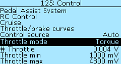
Five throttle modes options are available:
Speed — a similar mode is used in Infineon controllers and non-programmable low-cost controllers and is characterized by the use of maximum current to reach a given speed. In this mode, the maximum thrust is used until the desired speed is reached, the thrust is not regulated by the throttle grip.
Speed+torque — combined mode (as Kelly), similar to the operation of the gas pedal in a car with an internal combustion engine. In the case of selecting the Speed+torque mode, pressing throttle to 50%, when achieved 50% speed, the current consumption will be reduced to hold speed. The acceleration current will also be proportionally lower.
Torque — in this mode, the throttle controls phase current, the thrust is limited by the angle of rotation of the throttle.
Power+torque — In this mode, it is possible to drive an ebike like a motorcycle with an internal combustion engine. The response is similar to the throttle grip on internal combustion engines.
Power — in this mode, you can fine-tune the consumption from the battery using the throttle.
Adaptive throttle — this function allows you to more accurately dose throttle at high speed when the battery current in the settings is several times lower than the phase current. The default is set to 6%.
Throttle and brake voltage range setup
The menu items in the Controller > Control section allow you to set the voltage ranges of the throttle and brake grips.
Currently, voltage settings for all throttles and brakes are common.
# Throttle — shows the voltage of throttle grip connected to the controller, in volts (V).
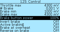
Throttle min and Throttle max — range of the throttle grip, in millivolts (mV). Select of values from 0 mV to 15 000 mV, in increments of 10 mV. If the maximum value is exceeded by 5%, protection against a broken throttle grip will be activated. If the range is incorrectly set, then when you fully press the throttle grip, the electric motor will turn off, in this case, you need to increase the range value.
# Brake — shows the voltage of the brake connected to the controller, in volts (V).
Brake min and Brake max — range of the analog brake lever, in millivolts (mV). Select of values from 0 mV to 15 000 mV, in increments of 10 mV.
Brake button power — braking force when pressing the brake button relative to the phase braking level, in percent (%). This setting allows you to adjust the level of braking force with the brake levers with integrated brake buttons.
Invert brake — inverts the voltage value from the built-in brake lever. Select On to enable. It is useful to enable when the voltage brake lever with reverse voltage is connected to the On-board computer and you want to use the value Auto in the menu item Controller > Control > Control source. The digital brake grip (i.e. button) connects to the On-board computer, see section Buttons setup.
Active braking — enables the brake to use the battery for stopping. Select of values On and Off.
Brake at overheat — enables full torque braking when the motor overheats. Select of values On and Off.
Lock throttle at brake — disables the throttle lever after the brake is applied until the throttle is fully released. Helps with throttle lever glitches, in this case, the Throttle lock flag will be set in the menu Status flags.
Reverse on brake — after stopping, pressing the brake lever again activates reverse. Select of values On and Off.
Boost mode
Boost duration (User level) — maximum power operation time, in seconds. Select of values from 0.2s to 10s, in increments of 0.2s. The function works as follows: in the Controller > Control modes menu, configure the battery current to be greater than the discharge current in the battery settings in the Controller > Battery > Discharge max menu. Next, select the boost operating time in the Controller > Controls > Boost duration menu. Now, while driving, when the battery current increases more than Discharge Max, the countdown of the time during which this excess will work begins, i.e. Boost. After this time, the battery current will be reset to the Discharge max setting level. In order for the boost mode to be available again, it is necessary to drive for 1 minute at a battery current value of no more than 70% of the Discharge max value.
For example, on the Sur-Ron Ultra Bee, this mode allows you to squeeze the maximum out of the standard battery and achieve a power of 21 kW instead of 12 kW.
Setup 100% speed value
The menu items in the Controller > Control section allow you to adjust the 100% speed level. The maximum speed in the field weakening mode is 150%.
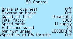
Speed ref. filter — filter mode selection. Select of values OFF, Linear, Quadratic, Cubic. For the control modes Speed and Speed torque, a speed reference filter is applied, for a smoother response to the throttle change. The filter algorithm calculates the difference between the previous speed request and the current one, multiplies the error by a power of 1,2,3 (linear, quadratic, and cubic, respectively), and multiplies by a factor. The resulting value is used as the cutoff frequency of the low-pass filter. The larger the change, the sharper the response to it.
Filter factor — sets the filtration factor. Select of values from 0 to 30000, in increments of 100.
Speed mode allows you to select the level of 100% speed and what it depends on:
- OFF — completely disables speed control PID.
- Middle U bat — the average value between the minimum and maximum voltage of the battery settings used as speed reference, depending on motor kV.
- U supply — supply voltage used as speed reference, depending on motor kV.
- Ref. speed — speed in km/h, is set by parameter Reference speed. The speed value is taken from the motor or from an external speed sensor connected to the controller.
- Ref. ERPM — speed in motor electric RPM, is set by parameter Reference speed.
Minimum speed — in electrical revolutions per minute (ERPM). Select of values from 0 ERPM to 100000 ERPM, in increments of 100 ERPM.
Speed lim. at 0% throttle — enables limiting the speed when the throttle grip is completely released. Select of values On and Оff. Selecting Off disables motor control when the throttle is released.
Motor setup
The Controller > Motor Setup menu contains all settings related to electric motor operation parameters.
Motor temperature sensor
In the menu section Controller > Motor setup > Motor t°-sensor you can select a temperature range in which a smooth power limit will occur (Delta °t parameter) and specify the maximum temperature (°t max).
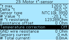
°t max — maximum electric motor temperature, in degrees Celsius (°C). Select of values from 50°C to 200°C, in increments of 1°C.
Delta °t — the temperature value that is deducted from the maximum temperature (°t max), the resulting temperature value will be the beginning of the power limit, in degrees Celsius (°C). Select of values from 1°C to 100°C, in increments of 1 °C.
In the menu item Sensor type you can select the following types of temperature sensors that support the controller — KTY81(82), KTY83, KTY84, NTC10K (B:3950), NTC10K (B:3380), PT1000. To disable the temperature control, select the value OFF.
It is recommended to install a temperature sensor so close as possible on the stator windings, while not in contact with the stator iron. If you don't know what kind of sensor is in the motor, you can check all types of sensors and select the one that displays data the most closely to room temperature. The current measured temperature is displayed at # Value °t.
The # °t resistance menu item displays the resistance of the motor temperature sensor, with an accuracy of +/-10%.
Resistance Offset — temperature sensor offset, in Ohms. Select values from -100 Ohm to 100 Ohm, in increments of 1 Ohm.
Temperature correction — temperature sensor correction with wire resistance. Select of values On or Off.
GND wire resistance — resistance of a ground wire, in Ohms. Select values from 0 Ohm to 1000 Ohm, in increments of 1 Ohm.
Sensors current — hall sensor current consumption, if temperature sensor uses common ground with hall sensors, in milliamps (mA). Select values from 0 mA to 100 mA, in increments of 1 mA.
# Total current: — calculated current, to check with a tester, in mA.
Clutch
In the menu section Controller > Motor Setup > Clutch you can configure a smooth engine launch for soft engagement clutch or freewheel. Useful for gear motors or mid-drives. At the moment, the setting works well only in the control mode Torque, because the clutch there is always engaged. An alternative option is to configure the acceleration limit in the modes S1, S2, S3 in the menu section Controller > Advanced modes.

The parameter Mode determines the way of operation::
Accelerate — smoothly accelerates the motor until the load appears.
Accelerate and hold — in addition to the previous one, it applies weak torque to the motor after the throttle is released, this mode allows you to switch speeds at mid-drive systems without using the pedals.
# Phase amps
Start time — maximum time for soft start, in seconds (s). Select values from 1s to 20s, in increments of 1s.
Start current — phase motor current at which the load will be detected and the soft start is disabled, in amperes (А). Select values from 0.2А to 50.0А, in increments of 0.2А. This value must be higher than the phase current for specified acceleration of the motor without load.
Detection time — the time during which the load must be present, after which the soft start will be switched off, in milliseconds (ms). Select values from 10 ms to 1000 ms, in increments of 10 ms.
Acceleration — value in volts/seconds (V/s). Select values from 2V/s to 1000V/s, in increments of 2 V/s. The higher the value, the more you need to specify Start current, since the motor will consume more current during acceleration.
Hold (20%) and Hold (80%) — two parameters regulating the phase current supplied to the motor in the mode Accelerate and hold, in amperes (А). 20% — current at low speeds, 80% — current at about maximum speed. It is possible to determine the approximate values by the no-load current of the motor. Select values from 0.2А to 50.0А, in increments of 0.2А.
Hold enable time — time through which after the throttle has been pressed, torque hold will become available, in seconds (s). Select values from 1s to 120s, in increments of 4s.
Hold time — the time during which torque will be applied after releasing the throttle, in seconds (s). Select values from 1s to 120 s, in increments of 1s.
Optimal settings for MAC motor: Accelerate, 15a, 50V/s, 200ms.
Setup the motor position sensors
Under the menu section Controller > Motor setup > Position sensors, you can find the menu items for configuring the position sensors of the electric motor. At the moment, the Controller supports two types of sensors — Hall sensors and a rotation angle sensor (encoder).
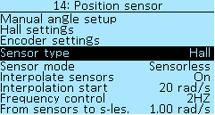
Sensor type — Parameter needs reboot if manually changed. There are currently two types of sensors available:
Hall — Hall sensors.
Encoder — rotation angle sensor.
Sensor mode — this parameter is loaded at start-up and can be saved. At the moment, the Controller has the following motor control modes:
Sensorless — motor control using BEMF integration, parameter Integration threshold is used. It is rather insensitive to tuning, but more accurate tuning may be required for high-speed motors (such as RC). At the moment, the sensorless does not have a start-up algorithm, it works stably only at some speed. Hall setups start with sensorless mode.
Combined — start the motor on Hall sensors, then switch to sensorless mode, the threshold is determined by the parameter radians per second (rad/s) in the From hall to s-less menu item. Select of values from 0.00 rad/s to 2.00 rad/s in increments of 0.05 rad/s. To convert values to RPM = 9.5493 * Pole Pairs * rad/s.
Sensors — electric motor control only by signals from Hall sensors.
Freq — frequency control. Do not use this mode for driving!
Interpolate sensors — smooth change of the sensors angle based on speed. Used for FOC mode. Select of values On and Off.
Interpolation start — the motor is always started from a discrete angle, if digital halls are used. After the specified speed, the angle starts to change smoothly. Select of values from 0 rad/s to 100 rad/s, in increments of 1 rad/s.
Frequency control — a separate mode that can be used to power equipment through a transformer or to dry the varnish on the motor windings. Select of values from 10 HZ to 200 HZ, in increments of 1 HZ.
Hall sensors setup
Further in the menu section Controller > Motor Setup > Position sensor > Hall settings there are items for additional setting of Hall sensors.
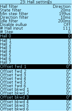
Hall filter — enable or disable the filter in the direction of rotation, select the Direction and OFF values.
State filter — select the delay time, in seconds (sec). Selection of values from 0.000s to 1.000s, in increments of 0.002s. This delay is used if the wrong value of the Hall sensors is received. All indicators that are less than the set value will be filtered out.
Min step filter — minimum hall switch time, in microseconds (µs). Select values from 25 µs to 5000 µs, in increments of 1 µs.
Direction filter — select the delay time for changing the direction of rotation of the electric motor (forward/backward), in seconds (sec). Selection of values from 0.000s to 1.000s, in increments of 0.002s.
Idle filter — when the motor is not moving, the sensor position is reset to the middle position. Selection of values from 10ms to 1000ms, in 5ms increments.
Disable pullup — disable hall pullup, mostly not needed. Select of values On or Off.
The next menu sections shows the Hall indices and Hall angles for the two directions of rotation of the electric motor. These indices are used for the internal operation of the Controller.
Manual setup the Hall sensors angles
In general, it is not recommended to change these settings manually!
In the menu section Controller > Motor settings > Manual angle setup you can set up the Hall sensors angles of the electric motor.
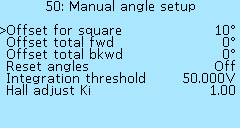
Offset for square — additional shift for square wave mode, in degrees (°). Select of values from -30° to 30°, in increments of 1°.
Offset total fwd — shift all Halls sensors by the specified value for the direct rotation of the motor, in degrees (°). Select of values from -60° to 60°, in increments of 1°.
Offset total bkwd — shift all Halls sensors by the specified value for the reverse rotation of the motor., in degrees (°). Select of values from -60° to 60°, in increments of 1°.
To shift all the halls, you must press the right button of the On-board computer, enter the shift angle, press the right button again. The value will be reset and the angle of all halls will change to the specified value. You can change the angle of the hall shift in the opposite direction by setting a negative value.
Reset angles — reset of all Hall sensors angles. Select of values On and Off.
Integration threshold — analogue of Hall angles for sensorless engine control mode, in volts (V).
Hall adjust Ki — the meaning of the coefficient is to find the midpoint of the position of the Hall sensors when adjusting them. Values from 0.02 to 5.00, in increments of 0.02. If the value of the coefficient is too small, then the tuning process will end before the midpoint is determined. If the value of the coefficient is too large, then the setting will not be completed and will stop by timeout, because the midpoint will not be found due to the angles changing too often.
Encoder setup
In the menu Controller > Motor Setup > Position sensor > Encoder settings there are menu items for configuring the motor encoder. The parameter values in each of the items will appear after passing through the Auto-setup procedure. Controllers with encoder capable have orange phase wires and an encoder speed of 580kHZ under Controller > Device Information. The wire for connecting the electric motor with the encoder is ordered separately and is installed instead of the wire with connector for the Hall sensors.
Note: on older controllers encoder use P1 input as PWM for initial position detection, setup ports P1 (I5) and P2 (I6) to OFF and disable PWM output. Settings applied after reboot.
Wiring and connectors Compatibility:
Halls > Encoder — if your controller has a connector for Hall sensors, then you can make an adapter for the encoder yourself. But, in this case, you will not be able to move when you turn it on, you will need to push the electric bike with your feet to start first time.
Encoder > Halls — if your controller has an encoder connector, then you can make an adapter for Hall sensors yourself. Everything will work.
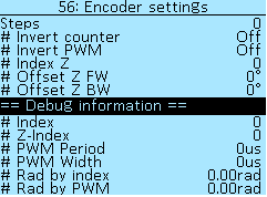
Steps — number of encoder steps, selectable in increments of 1.
# Invert counter — select of values Off and On.
# Invert PWM — select of values Off and On.
# Index Z — the value of the additional output signal of the encoder (zero pointer), the choice of values from 0 to 7, in increments of 1.
# Shift Z FW — signal shift, select of values from -60° to 60° in increments of 1°.
# Shift Z BW — signal shift, select of values from -60° to 60° in increments of 1°.
Debug information
Index — encoder index signal value.
Z-Index — the value of the zero pointer.
PWM Period — PWM signal period, in microseconds (µs).
PWM Width — PWM signal pulse width, in microseconds (µs).
Rad by index — position of the electric motor by index, in radians (rad).
Rad by PWM — position of the electric motor by PWM, in radians (rad).
Motor parameters
Items in the Controller > Motor setup menu section allow you to configure the parameters of the electric motor.
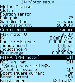
Pole pair — the number of magnetic pole pairs of the rotor of the electric motor determines the speed at which the motor shaft will rotate. This parameter is used to calculate RPM and speed. For a more accurate autodetection of the Hall sensors angles, you must specify the correct value for the number of pole pairs for your motor. For the most popular motors, you can see this value in the table Motor Information. If your motor is not listed in the table, check with the manufacturer for the number of pole pairs.
Spin direction — this setting allows you to change the direction of rotation of the electric motor. Select of values Forward and Invert. Or you can swap two motor phases to change the direction of rotation.
Gear ratio — additional motor reduction factor for motors with built-in gearbox. Simplifies setting wheel ratios for speed calculation.
Integration thr. — the analog of Hall sensors angles for sensorless motor control mode, in volts (V).
Control mode — this parameter is loaded at start-up and can be saved. At the moment, the Controller has the following motor control modes:
Off — control mode is disabled.
Square — outdated control method used only for motor detection.
FOC — field-oriented control of the motor.
DC-DC — charging mode when you use the controller in motor charging mode.
The control mode selected in this menu is the priority setting for the controller. If the Hall sensor mode is selected in the Controller > Motor setup > Position sensor menu, which does not correspond to the set operating mode of the electric motor, then this Hall sensor mode will be automatically replaced with a more suitable one.
Max motor U — limits voltage supplied to the motor, in volts (V). In most cases, this parameter is not needed. Select of values from 0V to 100V, in increments of 1V.
kV — motor parameter, electric revolutions per volt (eRPM/V).
Next are the menu items for configuring the MTPA, this function allows you to introduce a negative id current to increase the torque on the IPM motors.
Phase resistance — the result of measuring the phase resistance of the electric motor during auto-setup (menu item Motor LR), in Ohms (Ohm).
Inductance d — the result of measuring the inductance of the electric motor along the d axis during auto-setup (menu item Motor LR), in microHenry (µH). The d-axis (“straight”) refers to the component of the stator magnetic field that is in phase with the rotor magnetic field.
Inductance q — the result of measuring the inductance of the electric motor along the q axis during auto-setup (menu item Motor LR), in microHenry (µH). The q-axis (“quadrature”) refers to the component of the stator magnetic field that is 90 ° out of phase with the rotor magnetic field.
Flux linkage — is the total magnetic flux permeating the electrical circuit, in Weber (Wb).
FOC Optimization — changes the FOC PWM mode with a choice of Efficiency or Ripple. In Efficiency mode — reduces losses in the controller. In Ripple mode — reduces current ripple in the motor and, in some cases, slightly increases motor efficiency and reduces motor noise.
MTPA (IPM Motor) — enable (On) the MTPA function for IPM motor, for all other motors this function must be disabled (Off).
FOC Vq limit — improves field weakening on some motors. Select of values On and Off.
# Square wave settings:
Square offset — additional shift for square wave mode, in degrees (°). Select of values from -30° to 30°, in increments of 1°. This item is similar to the same item in the menu Controller > Motor setup > Position sensor > Manual angle setup.
Boost square current — in the sensorless or square mode, applies 100% PWM at the beginning of each winding switch. Starting from specified speed and minimum requested current. Select of values On and Off.
Boost current — setting refers to the control mode Square, the minimum current from which the rapid current pumping in the windings is turned on, in amperes (А). Select of values from 0A to 100A, in increments of 1A.
Boost speed — setting refers to the control mode Square, the minimum speed after which the rapid pumping of current in the windings is turned on, in radians per second (rad/s). Select of values from 0.00rad/s to 2.00rad/ms in increments of 0.05rad/s.
Battery
In the Controller > Battery menu section you can set up the parameters of the battery connected to the Controller. The Nucular controllers support supply voltages from 20V to 90V, this is 21S for Lithium-ion (Li-ion) batteries and 25S for Lithium-iron-phosphate (LiFePO4) batteries. To configure the battery, you must specify the range of supply voltage and current. To correctly display the battery capacity on the On-board computer screen and correctly calculate the remaining charge, you must specify the battery capacity in settings of On-board Computer. If you use several batteries with different parameters on the same bike, you can save the configurations for each battery on the SD card and load them after replacing the battery. The SD card can be stored in the On-board computer.
#Quick voltage setup — feature to help you select the correct parameters for your battery. To automatically configure the items Full charge, Supply max, Supply min, you need to select the type of battery chemistry from the following options:
LiIon (3.6V) for li-ion battery.
LFP (3.2V) for lithium-iron-phosphate battery (LiFePO4).
LTO (2.3V) for lithium-titanate battery (Li4Ti5O12).
Next, select the Cell count, values from 8S to 28S, in increments of 1S. After that, in the Apply setup item, select Yes. After saving the settings, you will see a window with new battery parameters. It is important to remember that we guarantee the operation of controllers with voltages up to 90V. The device is technically rated for 95V, but operating above 90V will void the warranty and you will be warned about this in a pop-up window. For example, if you try to select 22S for a lithium-ion battery. If the settings exceed 95V, the controller will also warn you that you are trying to set the voltage too high.
#Limits: section
Full charge — delta voltage relative to the maximum, at which when the controller is turned on, will reset the watt-hour consumption, in volts (dV). This setting resets the From charge statistics when the Controller is turned on. Select values from 0.00 dV to 10.00 dV, in increments of 0.3 dV.
Supply max and Supply min — battery voltage range, in volts (V). Select values from 20.00V to 95.00V, in increments of 0.1V. Also, these settings are used for the Converter mode.
For lithium-ion (Li-ion) batteries, the minimum can be considered 2.8V*S, the maximum 4.2V*S.
For lithium-iron-phosphate (LiFePO4)-minimum 2.7V*S, maximum 3.6V*S.
We guarantee stable operation of the Controller at voltages up to 90V inclusive. Using a battery over 90V may damage the Controller and void the warranty.
Charge max — maximum battery charging current, during regeneration or in Converter mode, in amperes (А). Select values from 1.0A to 400.0А, in increments of 0.5А.
Discharge max — maximum continuous discharge current of the battery, but in boost mode, it can be more, check (Throttle control mode setup.), in amperes (А). Select values from 1.0A to 400.0А, in increments of 0.5А.
Power max — maximum continuous discharge power, in watts (W). Set 0W to deactivate power limit. Select values from 0W to 30000 W, in increments of 100W.
# DC voltage — current supply voltage of the Controller, in volts (V).
Converter
In the menu section Controller > Converter, can configure charging mode from the power supply through the motor. Charging through the inductor is not currently supported. For the power supply connection diagram, see this link.
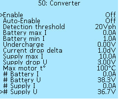
Enable — turn on the converter mode and start charging. Select of values On and Off.
Auto-enable — allows the automatic start of charging when the charging PSU is connected to the controller. Select of values On and Off.
Detection threshold — minimum voltage on phases when charger mode activates, also disables motor control, in volts per phase (Vph). Select of values from 10Vph to 80Vph, in increments of 1Vph.
Battery max I — maximum battery charge current, if no value is specified then battery settings are used, in amperes (А). Select of values from 0.0А to 100.0A, in increments of 0.5А.
Battery min I — minimum charge current when current is decreased by voltage, in amperes (А). Select of values from 0.5А to 10.0A, in increments of 0.5А.
Undercharge — voltage relative to maximum battery voltage setup, in volts (V). Let's decrease the full charge voltage. Select of values from 0.00V to 10.0V, in increments of 0.1V.
Current drop delta — decreases charging current down to Battery min I as the battery reaches maximum voltage on specified voltage range, in volts (dV). Select of values from 0.0dV to 20.0 dV in increments of 0.5 dV.
Supply max I — maximum power supply current, in amperes (А). Select of values from 2.0 A to 150.0 A, in increments of 0.5 A.
Supply drop U — allowable voltage drop on wires or power supply, in volts (V). Select of values from 0.50 V to 10.00 V, in increments of 0.25 V.
Max motor t° — setting the limitation of the heating temperature of the motor during charging, in degrees Celsius (°C). Select of values from 50°C to 120°C, in increments of 5°C.
MPPT — enables and disables the maximum power point tracking feature when charging the battery through the controller from a solar panel.
Below in the menu section, through the # sign, the real-time values of voltages, currents and power are shown:
# Battery I
# Battery U
# Charging power
# Supply I
# Supply U
After plugging in the power supply, the On-board Computer will display the battery charging process.
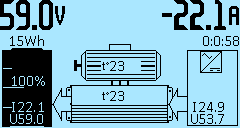 Indication to the right:
-22.1A — information line parameter, depending on the On-Board Computer settings.
0:0:58 — time elapsed since charging started, hours, minutes, seconds.
I24.9 — charging current, in Amperes (A).
U53.7 — charging voltage, in Volts (V).
The indication in the middle is the temperature of the motor and the controller, respectively, in degrees Celsius (°C).
Indication to the left:
59.0V — information line parameter, depending on the On-Board Computer settings.
15Wh — the battery capacity in Watt hours (Wh).
100% — the battery level, in percent (%).
I24.9 — the battery current, in Amperes (A).
U53.7 — the battery voltage, in Volts (V).
I/O port configuration
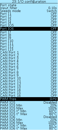
In the Controller > I/O configuration menu section, you can configure the port's functions. The controller has thirteen digital ports that can be configured for different functions — I1-I4, IO5, IO6, I7-I13. See section Connection diagram.
Sixteen CAN ports are additionally available CAN port 1 - CAN port 16, the signal source for which can be configured on the On-board computer or uLight. These are software values, there are fewer physical inputs on the boards, at the moment there are eight CAN ports IO1 - IO8 available in the On-board computer plus four Hotkeys (buttons on the On-board computer). In the future, six CAN ports I1 - I6 will be added to the uLight board.
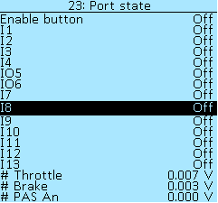
In the section Controller > I/O configuration > Port state, you can check input activation when contact shorted to GND. When a signal is applied, the value will change from Off to On. Below in the menu items # Throttle and # Brake you can see the voltage on the throttle and brake levers, respectively.
If the controls are connected to the On-board computer, then it is necessary to check the activation when contact shorted to GND in the On-board computer > Information menu.
# PAS An — shows an analog PAS sensor voltage, in volts (V).
In the item Controller > I/O configuration > Speeds mode you can select the method for switching additional modes S1, S2, S3 for inputs in the Controller or CAN inputs - Switch or Buttons.
Available functions for the Controller ports I1, I2, I3, I4, IO5, IO6, I7, I8-I13 and CAN ports CAN port 1 - CAN port 16:
OFF — disable port.
Spec. — special port function (like PWM or PAS).
RV — reverse.
CRe — enable cruise.
CR+ — increment cruise speed (when the cruise is active).
CR- — decrement cruise speed (when the cruise is active).
CRr — restore the last saved cruise speed with the button, activated only above min cruise speed.
BK — brake button.
DM — disable motor (disable throttle, brake, and PAS).
DTH — disable throttle.
DPAS — disable PAS.
P+ — PAS power level increase.
P- — PAS power level decrease.
SWSNS — input for Gearsensor to reduce motor torque (WIP). In development.
N — activates the neutral mode forcibly, resets speed mode counter if used. If neutral is activated by default, you need to change speed mode again to exit neutral.
ENTH — enable throttle.
nBK — inverted brake button input, activates the brake when the contact is opened.
S1 — speed 1.
S2 — speed 2.
S3 — speed 3.
S1of3 — speed 1 for 3-position switch.
S3of3 — speed 3 for 3-position switch.
Scyc — cycle speed mode, sequential switching with one button.
S++ — increment speed, switching the speed from low to high with one button.
S– — decrement speedи, switching the speed from high to low with one button.
SPSNS — input for external speed sensor.
CL1-CL5 — instant configuration import by pressing the CAN button (up to five different configurations). For correct import, the function number must match the number in the name of your configuration file. For example, a CL3 function would correspond to a file called ncconf3.cfg.
Further in the menu, there are items for configuring the PWM outputs.
PWM output setup
To activate the PWM IO5 or PWM IO6 output, the Controller > Port Setup menu should be set to Spec. mode and PAS disabled.
PWM freq — selection of frequency of additional PWM output on ports P1/P2. Select of values PWM frequency — 100Hz, 500Hz, 1kHz, 5kHz, 10kHz, 24kHz (FAN). For a conventional light bulb, large values are not needed. Select the frequency 100Hz, this will be enough to avoid flickering. The high frequency marked FAN is used to control the fan, this is their standard frequency.
PWM IO5 and PWM IO6 — selection of operating modes:
- Disabled — mode not selected.
- Stop-light — activated when the brake is pressed.
- Headlight — activated when the controller is enabled.
- t°C motor — activated beyond the two deltas of the motor temperature, as the motor heats up will increase the PWM duty ( Delta °t set up on menu Controller > Motor setup > Motor t°-sensor).
- t°C controller — activated from 40°С, maximum value at 80°С temperature of the Controller.
PWM IOn Min / Max — indicates the output range of the PWM (duty), select of values from 0% to 100%, in increments 1%.
PWM IOn t° Min / t° Max — selection of motor or controller temperature, select of values from 0°С to 100°С, in increments 1°С.
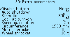
Extra parameters
In the menu section Controller > Extra parameters you can set up various additional settings of the Controller.
The power button and auto shutdown
The controller power button is located on the back of the On-Board Computer. In the Controller > Extra parameters > Disable button menu item, you can select the way to turn on/off the Controller, which turns on when it is powers-up or the button contacts are closed. In the off mode, the controller consumes about 100 μA, so if you reconnect the power supply without discharging the capacitors, the controller may not start.
Selecting modes for Disable button:
None — the controller turns on when it is power-up up or when the power button is closed, does not turn off.
Switch — the controller turns on when the power button is closed (when EN shorted to GND), turns off when it opens.
Button — the controller turns on the button on the On-Board Computer, press it for 2 seconds, and release, to disable it, press and hold the button again.
CAN — the controller turns on when it is powers-up or the button contacts shorts, disables only when another device on CAN bus will send a request to disable. This function is used when there are several controllers on a system, where one of them is set to button or switch mode, and the other in CAN mode.
Auto shutdown — activation of the controller shutdown function after a while if the motor does not spin. Select of values On and Offл. The shutdown time is set in item Sleep time.
Sleep time — selection of the controller shutdown time when the Auto shutdown function is activated, in seconds, (s). Select of values from 30s to 1500s, in increments of 5s.
Lock at turn-on — the function locks controller inputs when enabled until the password is entered on the On-Board Computer, if there is no On-Board Computer, enabling this setting will permanently lock the controller.
Speedometer setup
The next block of settings in the menu section Controller > Extra parameters refers to the speed calculation setting. If you use an external speed sensor connected to the On-board computer, you need to configure it in menu Data source setup.

Speed calculation — enabling speed calculation in the Controller. Useful for multi-motor configurations, you can turn off the speed calculation on some motors. Select of values On and Off.
Circumference — wheel circumference, in millimeters (mm). Select of values from 0mm to 3000mm, in increments of 5mm. To calculate the circumference, you can use online calculator.
Motor sprocket — this setting specifies the number of sprocket teeth on the motor (notional), which allows you to set the gear ratio from motor shaft to the wheel. Also, this setting can be used as a reduction ratio for gear motors.
Wheel sprocket — the number of teeth of the wheel sprocket, similar to the setting Motor sprocket.
If you have a wheel motor, then in the section Controller > Motor setup you need to specify the number of Pole pair (divide the number of magnets by two). For gear motors or mid-drives, it is recommended to install an external speed sensor that connects to the Onboard computer or to any of the controller ports.
Master-controller
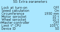 In the menu section Controller > Extra parameters > Master-controller you can enable the function of controlling other controllers from the current one. This setting is suitable for multi-motor configurations where control (throttle, brake and etc.) is connected into one of the controllers directly.
Other settings
 Limit t° CPU — limiting the temperature of the processor, in degrees Celsius (°C). When the specified threshold is reached, the phase current will be limited. Select of values from 60°C to 105°C, in increments of 5°C.
Device ID — setting the Controller number in the CAN network. This number is displayed in the menu section Settings > Devices in front of each device that is connected to the network using the LEVCAN protocol. If, by default, your device number is 0, we recommend changing it to another number for the correct firmware update.
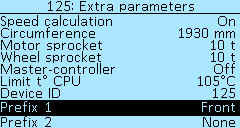
Prefix 1 and Prefix 2 — controller name setting for multi-motor configurations. Using the prefixes together or separately, you can specify where the electric motor that the Controller controls is located. The selectable values for each prefix are None, Front, Rear, Left, Right. To save the setting, go to the Controller > Save settings menu item and select On, then restart the controller. The prefix will now appear in front of the controller name in the Devices menu.
For example, you have a 2WD scooter and two 12F controllers, you need to distinguish them somehow in the Devices menu for easy setup. A controller for a front motor can be prefixed with Front, in which case the controller will be named Front Nucular controller in the Devices menu.
If you are using a 3WD drive or more, then both prefixes must be used for the controller name. For example, if the controller is driving a rear right motor, the setting will look like this: Prefix 1 — Rear, Prefix 2 — Right.
Access level
Four levels are available:
Novice
User
Advanced
Engineer
Depending on the selected access level, some menu items will be hidden to make it easier to configure the controller. For example, at the Novice level, a minimum basic set of settings will be displayed. At the Engineer level, all possible settings will be available. You can choose your level yourself.
Important note: now after updating the firmware to v0.8.13, the default level will be set to Novice. Remember this when you don’t find the usual menu items in the controller settings.
PID regulators
In the Controller > PID regulators menu section, various signals of proportional-integral-derivative (PID) regulators are configured - devices in the control loop with feedback used in automatic control systems to generate a control signal in order to obtain the required accuracy and the quality of the transition process. Settings for advanced users.
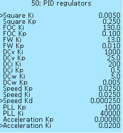 Two or three coefficients are used for the settings of each regulator:
Ki — integral coefficient.
Кp — proportional coefficient.
Kd — differentiating coefficient.
Square Ki, Kp — phase current regulator for a square wave.
FOC Ki, Kp — phase current regulator for FOC mode.
FW Ki, Kp — field weakening coefficients.
DCv Ki, Kp — voltage regulator on the DC bus.
DCi Ki, Kp — current regulator on the DC bus.
DCw Ki, Kp — power calculator.
Speed Ki, Kp, Kd — speed regulator for throttle control modes Speed and Speed torque.
PLL Ki, Kp — speed regulator for motor angle interpolation.
Acceleration Kp, Ki — deceleration and acceleration regulator.
Status flags
The Controller > Status Flags menu section displays errors that may occur during the operation of the Controller. If an error occurs, the parameter value changes to On.
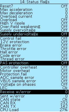
Reset? — reset all statuses. Values On and Off.
Max acceleration — maximum acceleration, in ERPM/s.
Min deceleration — maximum deceleration, in ERPM/s.
Overload current — the last recorded current on the phases, in Amperes.
Overload — exceeding the permissible current values. Values On and Off.
High V ripple — overcurrent on the P24F controller (plate) which is monitored via voltage ripple. Values On and Off.
Over-Field weakening — weakening error. Values On and Off.
Supply overvoltage — too high supply voltage, the error will appear above 95V, but in general depends on the controller model. Values On and Off.
Supply undervoltage — too low supply voltage, less than the minimum battery supply threshold. Values On and Off.
12V protection — error on the 12V power line. Values On and Off.
Control fail — the controller was not able to smoothly turn off the electric motor in time when throttle released. May happen with certain motors when field weakening used, decrease FW current. Values On and Off.
12V protection — breaking down or error on the 12V power line. Values On and Off.
Brake error — brake lever connection error. Values On and Off.
Throttle error — throttle lever connection error. Values On and Off.
Throttle lock — indicates that the throttle lever is disabled. Values On and Off.
Position sensor error — motor position sensor connection error. Values On and Off.
Square index error — signal error from sensors when trapezoidal control. Values On and Off.
Thread error — processor overload. Values On and Off. The error is not critical, let us know if it occurs.
PAS protection — PAS error. Values On and Off.
Controller overheat — overheat protection of the controller. Values On and Off.
Motor overheat — overheating protection of the electric motor. Values On and Off.
Protection fail — hardware error, malfunction of all protection systems during controller self-test. If this error occurs, the operation of the Controller will be impossible. Values On and Off.
ADC sample error — software error of the analog-to-digital converter (ADC). Values On and Off.
VBUS sample error — supply voltage measurement error. Values On and Off.
Voltage on phases — overvoltage on phases. Values On and Off.
LEC — types of errors on the CAN bus. If everything is alright you will see the value Ok. In case of errors, there will be values - Stuff, Form, Acknowledgment, Bit recessive, Bit dominant, CRC, SW. Tell us the code if this error occurs.
Receive w/error — CAN-bus errors on receiving.
Sent w/error — CAN-bus errors on transmitting.
CAN state — overloading buffers. If everything is alright you will see the value Ok. In case of errors, there will be values - OVR0, OVR1, OVR01. Tell us the code if this error occurs.
CAN RX — the number of messages in the CAN bus to receive.
CAN TX — the number of messages in the CAN bus to transmission.
CPU Load — current load of the central processor, in percentage (%).
Debug information
The menu section Controller > Debug information shows the main parameters of your Controller, electric motor, and the whole system - temperature, rpm, voltage, and current, as well as the values of the current regulators.
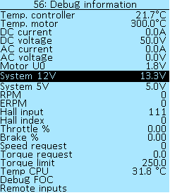
Temp. controller — temperature of the Controller, in degrees Celsius (°C).
Temp. motor — temperature of the electric motor, in degrees Celsius (°C).
DC current — DC current, in amperes (А).
DC voltage — DC voltage, in volts (V).
AC current — AC current, in amperes (А).
AC voltage — AC voltage, in volts (V).
Motor U0 — DC voltage on phases, in volts (V).
System 12V — voltage on the CAN bus 12V, in volts (V).
System 5V — voltage on the CAN bus 5V, in volts (V).
RPM — motor speed, in RPM (RPM).
ERPM — electric revolutions of the motor per minute (ERPM).
Hall input — this parameter allows you to check the functionality of the Hall sensors. There are three digits in this item, each shows the signal level, if you rotate the motor slowly by hand, all three digits should change. If none of the digits change, check if the Hall connector is connected or the ground may be broken. If one of the digits does not change - there is no contact or the sensor wire is broken. To check the contacts in the controller, disconnect the Hall connector and measure the voltages on the controller connector. There should be about 4V on the signal lines of the Halls, 5V on the power supply, and about 3V on the temperature sensor line.
Hall index — virtual position of the motor, digits from 1 to 6 (normal operation).
Throttle % — the percentage of how much the throttle is pressed.
Brake % — the percentage of how much the brake is pressed.
Speed request — set point for the speed regulator, in eRPM.
Torque request — phase current request, either positive throttle or a negative brake.
Torque limit — current limit for this type of controller, taking into account overheating.
Temp CPU — CPU temperature, in degrees Celsius (°C).
Next in the menu are the sections Debug FOC and Remote inputs, which are described below.
Debug FOC
In the menu section Controller > Debug information > Debug FOC
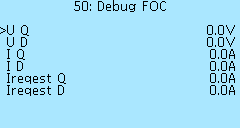
U Q — Q-axis voltage, in volts (V).
U D — D-axis voltage, in volts (V).
I Q — Q-axis current, in amperes (А).
I D — D-axis current, in amperes (А).
Ireqest Q — Q-axis current request, in amperes (А).
Ireqest D — D-axis current request, in amperes (А).
Remote inputs
In the menu section Controller > Debug information > Remote inputs you can view the parameters of the throttle and brake levers connected to other devices connected to the CAN-bus (On-board computer or uLight).
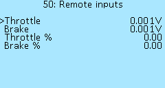 Throttle — voltage on the throttle lever at a remote source (On-board computer or uLight), in volts (V).
Brake — voltage at the brake lever at a remote source (On-board computer or uLight), in volts (V).
Throttle % — the percentage of how much the throttle pressed at a remote source.
Brake % — the percentage of how much the brake pressed at a remote source.
Logger
In the Controller > Logger menu section, you can enable and configure the data logging during the operation of the Controller. This functionality is experimental, errors may occur. The file is saved in CSV format to an SD card inserted into the On-board computer. To view the file, you can use the service Datazap. The SD card must have a FAT32 file system.
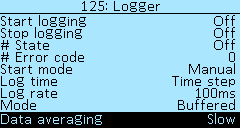
Start logging — to start recording, select On and press the right button of the On-board computer. After that, the #State menu item will change to Waiting status. The recording will start automatically after pressing the throttle grip. If an error occurs during the recording process, you will see its code in the # Error code menu item. In case of an error, firstly, check that the SD card has the FAT32 file system, and secondly, that there is free space on the SD card for recording. Additionally, you can delete unnecessary files from the card. After that, restart the Controller and start recording again. If the error repeats, contact us through the website or chat technical support and report the error code.
Stop logging — stop recording, select On to end recording.
Continuous logging — allows you to activate the continuous logging mode, including during stops. In firmware before v0.8.12 the log was written only during driving and electric motor operation.
Start mode — selection of recording start mode:
- Manual — enable manual recording.
- At start — recording starts automatically when the Controller is turned on.
Log time — two parameters of time for recording to choose from:
- Time step — delta of time since the previous record.
- Sys time — global time, which is incremented after the start of the controller.
Log rate — delay between records of values. You can choose either the number of PWM cycles (PWM1, PWM2, PWM5, PWM10), either time (1ms, 10ms, 20ms, 100ms, 1s, 5s, 10s, 30s).
Mode — recording mode selection:
- Buffered — buffering and recording in segments.
- Max rate — continuous recording mode.
Data averaging — using filters while recording:
- None — filter disabled (records real values).
- Fast — slight averaging (smoothes values).
- Slow — large averaging.
Add header to log — adding the name of the controller when writing the log, so that you can understand which controller the log belongs to in multi-motors configurations. You can set the name of the controller in the menu Controller > Extra parameters, items Prefix 1 and Prefix 2.
Next, in the # Data to log menu sections, you can select the set of parameters you want to record. Select On to enable parameter recording.
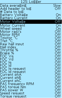 # Data to log:
Battery Voltage — battery voltage data logging.
Battery Current — battery current data logging.
Motor Voltage — motor voltage data logging.
Motor Current — motor current data logging.
Wheel speed — wheel speed data logging.
Motor rad/s — data logging of the angular speed of the electric motor.
Motor RPM — data logging of revolutions of an electric motor per minute.
Tmotor °C — data logging of the electric motor temperature.
Tfet °C — data logging the temperature of field-effect transistors.
Raw hall input — data logging the input status from Hall sensors without filter.
Hall index — virtual position of motor.
Throttle % — throttle grip data logging.
Brake % — brake lever data logging.
FOC Vq — Q-axis voltage data logging.
FOC Vd — D-axis voltage data logging.
FOC Iq — Q-axis current data logging.
FOC Id — D-axis current data logging.
FOC Iq request — Q-axis current request data logging.
FOC Id request — D-axis current request data logging.
Current phA — data logging the current on the A phase of the electric motor.
Current phB — data logging the current on the B phase of the electric motor.
Current phC — data logging the current on the С phase of the electric motor.
PAS frequency RPM — PAS frequency data logging.
PAS torque Nm — PAS torque data logging.
PAS power W — PAS power data logging.
Speed request — speed request data logging.
Torque request — torque request data logging.
Statistics
In the menu section Controller > Statistics you can view the data on the Controller. These are trip statistics that will be automatically reset when the controller is powered off. If you have several Controllers in the system, then you can see the summary data for all controllers in the general statistics in the On-board computer.
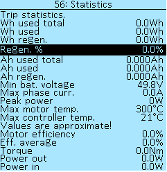
Wh used total — total energy consumption (used plus regen), in Watt-hours (Wh).
Wh used — energy consumption, in Watt-hours (Wh).
Wh regen. — energy gained during the recuperation process, in Watt-hours (Wh).
Regen. % — the percentage of energy recovered during recuperation (%).
Ah used total — total energy consumption (used plus regen), in Ampere hours (Ah).
Ah used — energy consumption, in Ampere hours (Ah).
Ah regen. — energy gained during the recuperation process, in Ampere hours (Ah).
Min bat. voltage — minimum battery voltage, in Volts (V).
Max phase curr. — maximum phase current, in Amps (A).
Peak power — maximum motor power, in Watts (W).
Max motor temp. — maximum motor temperature, in degrees Celsius (°C).
Max controller temp. — the maximum temperature of the Controller, in degrees Celsius (°C).
The values below are approximate!
Motor efficiency — efficiency of the electric motor, in percent (%).
Eff. average — average efficiency of the electric motor, in percent (%).
Torque — current torque of the electric motor, in Newton-meters (Nm).
Power out — the power that the electric motor delivers, in Watts (W).
Power in — power supplied to the electric motor, in Watts (W).
Device information
In the menu section Controller > Device Information you can view the basic information about the Controller. In this menu, you can check which firmware version is loaded into your Controller, as well as other parameters that differ depending on the Controller model.
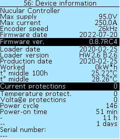
Nucular Controller — device name depending on the type of Controller.
Max supply — 95V. The warranty covers supply voltages up to 90V inclusive.
Max current — the value of the maximum phase current, depending on the type of Controller, in amperes (A).
Encoder speed — 26kHz or 580kHz (new Controller version with orange phase wires).
Firmware date — firmware compilation date.
Firmware ver. — version of the installed firmware, you can check for updates in the section Firmware.
Loader date — the data loader compilation date.
Loader version — data loader version.
Production date — date of manufacture of the controller.
Worked — operating time of the Controller in kilowatt-hours (kW*h).
t° middle 100 h — the average temperature of the Сontroller over the last 100 hours.
t° middle — the average temperature of the Сontroller over all time.
Current protections — the number of triggered overcurrent protections over all time of operation of the controller.
Temperature protections — the number of triggered temperature protections over all time of operation of the controller.
Voltage protections — the number of triggered voltage protections over all time of operation of the controller.
Power cycle — number of controller switching on.
Power-on time — total operating time of the Controller, minutes, hours, days.
Serial number — serial number of the Controller (for devices manufactured from 01 Jul 2022). Take a photo or write down this number and keep it separate from the Controller. You may need it when requesting repairs or if the Controller is stolen. After updating the firmware to 0.8.7, in some versions of controllers manufactured before 01 Jul 2022, a serial number may also appear. Check after update. date.