meta data for this page
On-board computer (v0.82B)
The On-board computer is equipped with a large sunlight-resistant screen to display main parameters, driving modes settings, software updates for all system components, battery control, and the charging state of the devices via USB. On the left side of the On-board computer there is a slot for a microSD card, which is used to update the firmware, save screenshots, import and export configurations and settings of the On-board computer and Controller. On the back of the On-board computer there is a power button, which is configured in the menu Devices > Controller > Extra parameters > Disable button.
Technical specifications:
- LCD size 3.6“
- FSTN, monochrome
- Screen resolution 240×128 px
- Screen heating
- RGB-button backlight
- MicroSD slot
- USB-charger 5.2V 2А
- Password protection
- Multi-Language (English, Russian)
- IP54 class
In the kit:
- GoPro fork mount.
- USB charging wire.
- PHD 2.0 4P connector — 4 pcs.
- PHD 2.0 6P connector — 1 pcs.
- PHD 2.0 8P connector — 1 pcs.
- Pins for crimping — 26 pcs.
- If you don't have a crimping tool, you need to order “Crimped wires for the Display”.
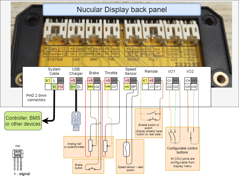
Connection diagram
You can look at the connection diagrams for other devices at this link. By default, all control devices (thumb throttle, brake levers, switches, etc.) are connected to the ports located on the back of the On-Board Computer. To access, you need to unscrew five screws and remove the plastic cover. For connection, PHD 2.0 connectors and crimp pins are used, which are included in the kit. If you do not have a crimping wire tool, for example, SN-2549, then you need to order “Crimped wires for Display”. The On-board computer is connected to the Controller with one CAN-wire 1.2 meters length, which is included in the Controller kit. Note, the CAN-wire from the Controller should be connected to the SYSTEM port on the On-Board Computer.
If you want to connect control devices directly to the Controller, you need to order “Controller-side inputs”, in the diagram at the link above this switching option is designated as “Alternative connection”. You can also use a mixed connection option, for example, connect the thumb throttle to the On-board computer, and the brake levers to the Controller.
The main screen overview
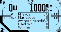
The screenshot below is one of the Main screen configurations. The layout of the elements on the screen depends on the theme and settings. In this example, the Hurma theme is installed.
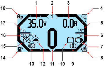
1. Information line, the content of which is changed by up and down keys. By default, the supply voltage is displayed in Volts (V). You can set up this line in the menu On-board computer > Main screen setup > Information lines (variable from the left side).
2. The currently active control mode. Setting the menu section Controller > Control Modes.
3. Information line, the content of which is changed by up and down keys. By default, the battery current is displayed in Amps (A). You can set up this line in the menu On-board computer > Main screen setup > Information lines (variable from the right side).
4. Controller temperature bar.
5. Controller temperature graph in degrees Celsius (°C). Setting the levels in the menu On-board computer > Main screen setup > Bar graph settings. You can change to degrees Fahrenheit (°F) in the On-board computer > Main screen setup > Temperature unit.
6. Motor temperature level in degrees Celsius (°C). Setting the levels in the menu On-board computer > Main screen setup > Bar graph settings. You can change to degrees Fahrenheit (°F) in the On-board computer > Main screen setup > Temperature unit.
7. Motor icon — motor/controller error. The cause of the error you can find in the Controller > Status flags.
8. Electric motor temperature bar.
9. B icon — braking. Indicates that the brake is currently activated.
10. Battery icon — battery failure. Check that the battery is connected correctly and that the BMS is working properly.
11. Speedometer in km/h or fast statistics, when the speed is zero. You can change to miles per hour (mph) in On-board computer > Main screen setup > Speed unit. The display of quick statistics is enabled in the menu On-board computer > Main screen setup > Quick statistics.
12. Turtle icon — battery voltage limit. It is triggered by the lower limit. Limit setting in the menu item Controller > Battery > Supply min. If the “turtle” lights up on a half-charged battery, reduce the battery current.
13. B! icon — braking limit. Indicates that the battery is fully charged and regen is not possible.
14. Battery charge bar.
15. Speedometer icon — cruise control is activated. Setting in the menu Controller > Control > Cruise.
16. Remaining battery charge in Watt-hours (Wh). Setting in the menu On-board computer > Main screen setup > Battery capacity.
17. Phase current in Amperes (A).
18. Phase current bar.
Menu navigation
Navigation on the On-board computer screen is carried out by the four bottom buttons. By holding down the two central buttons, you can take a screenshot of the screen, the file will be saved in .bmp format on the microSD card (if it is inserted into the On-board computer). Functions of the On-board computer buttons, from left to right:
- Switch the menu screen, cancel, return to the previous menu
- Switch up, less
- Switch down, more
- Select, apply
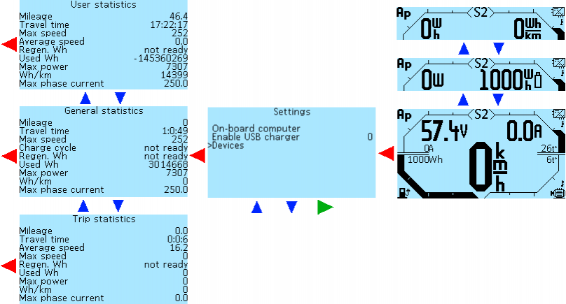
The picture below shows the menu navigation diagram, the red arrow is the left button, the blue arrows are the two central buttons, the green arrow is the right button of the Onboard computer.
Statistics
To go from the main screen to the statistics section, double-click the left button of the On-board computer. Then, with the second and third buttons, you can switch screens with statistics General statistics > User statistics > Trip statistics > From charge statistics.
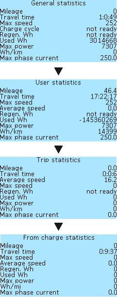 There are four types of statistics available:
General statistics — statistics for all time of using the Controller and On-Board Computer.
User statistics — statistics for any time period you choose. You can reset the data when you need it.
Trip statistics — statistics since the Controller was turned on.
From charge statistics — statistics between battery charges.
The list of parameters that are displayed for each type of statistics are the same and are calculated based on the type of statistics, with the exception of the Charge Cycles in the General statistics, instead of this item, in all other types of statistics is displayed the Average speed indicator, which is calculated while driving.
Mileage — mileage in kilometers or miles (depending on settings).
Travel time — driving time, hours, minutes, seconds.
Max speed — maximum speed, km/h or mph (depending on settings).
Charge cycle — number of battery charging cycles (for General statistics only).
Average speed — average speed, km/h or mph (depending on settings).
Regen Wh — the amount of energy returned to the battery during regenerative braking, in watt-hours (Wh).
Used Wh — the amount of energy consumed, watt-hours (W*h).
Max power — maximum power, watts (W).
Wh/km (Wh/mi) — the amount of consumed watt-hours of the battery per kilometer (or per mile) of run, (Wh/km or Wh/mi).
Max phase current — maximum phase current, amperes (A).
Statistics reset:
General — go to the General statistics screen, press and hold the left button of the On-board computer, the system will ask for a password, enter the default password or your custom password. For more information on setting up a password, read the Password setup section. After entering the password, the statistics will be reset. If you do not enter the password, then you can return to the main menu only after restarting the On-board computer. You can do this either by deactivating or using the button on the back of the Trip Computer, provided that you have configured it in the section Devices > Controller > Extra parameters > Disable button.
User — go to the User statistics screen, press and hold the left button of the On-board computer, the statistics will be reset.
Trip — statistics are reset automatically after controller shutdown.
From charge — statistics are reset automatically after full battery charging.
Menu and settings overview
Pressing the left button on the On-board Computer on the Main screen will take you to the Settings menu.
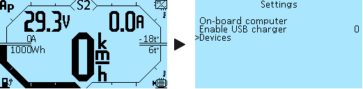 On-board computer — setting the parameters and functions of the On-board computer.
Enable USB charger — enable USB charging, see below for setting description.
Devices — list of all connected devices and transition to the menu of each of them for setting.
USB charger setup
A USB cable for charging your gadgets is included in the kit and plugs into the USB port on the rear panel of the On-Board Computer. To enable charging, go to Settings > Enable USB charger, press the right button to select, and then change the value from 0 to 1 with the third button. Then press the right button to save the value and turn on USB charging. If you want the USB charging to be always active when the On-Board Computer is switched on, go to On-Board Computer > Save and save this setting. If this is not done, then when the On-Board Computer is turned on again, the USB charging will be disabled
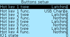 You can also configure the activation of charging by pressing and holding one of the buttons on the On-Board Computer (Hot key). To configure this function, go to On-board computer > Buttons setup, select which button you want to enable charging. Next, select the Latching in Hot key type and the USB Charge in Hot key func. In the screenshot, we made such a setting for the first button of the On-board computer (Hot key 1). After setting, go to the On-board computer > Save and save. Done. USB charging can now be turned on/off by pressing and holding the first button of the On-Board Computer when the main screen is displayed.
Information
The menu section Onboard computer > Information displays data from all sensors and devices connected to the Onboard computer.
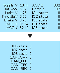 Supply V — CAN bus supply voltage, Volts (V).
Int V — internal power supply and USB-output voltage, Volts (V).
Light V — light sensor voltage, volts (V).
Throttle V — throttle handle voltage, Volts (V).
Brake V — brake handle voltage, Volts (V).
ACC X — accelerometer readings X-axis.
ACC Y — accelerometer readings Y-axis.
ACC Z — accelerometer readings Z-axis.
Comp t — On-board computer processor temperature, degrees Celsius (°C).
IO1 state — input IO1 of the I/O1 port on the rear panel of the Onboard computer (see the diagram in the Connection section), the value changes from 0 to 1 when the button connected to the Onboard computer is pressed, see the Buttons setup section, the other inputs have are the same values
IO2 state — input IO2 of the I/O1 port.
IO3 state — input IO3 of the I/O1 port.
IO4 state — input IO4 of the I/O2 port.
IO5 state — input IO5 of the I/O2 port.
IO6 state — input IO6 of the I/O2 port.
IO7 state — input IO7 of the THR (Throttle) port.
IO8 state — input IO8 of the BRK (Brake) port.
CAN_OVR — CAN bus receive overrun.
CAN_LEC — CAN bus last error code. Tell us the code if this error occurs.
- 0: No Error
- 1: Stuff Error
- 2: Form Error
- 3: Acknowledgment Error
- 4: Bit recessive Error
- 5: Bit dominant Error
- 6: CRC Error
CAN_TEC — CAN bus transmit error counter.
CAN_REC — CAN bus receive error counter.
Settings saving
All made settings can be saved in the menu On-board computer > Save. Press the right button of the On-board computer to save. If you do not save the settings, they will be reset after a restart.
Buttons backlight
In the menu On-board computer > On-board computer settings > Button color and brightness, you can customize the color of the buttons of the On-board computer.
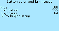 Hue — adjustment of the button illumination color, values from 0 to 255, in 1 increments.
Saturation — adjustment the saturation of the button illumination, values from 0 to 255, in 1 increments.
Lightness — adjustment the brightness of the button illumination, values from 0 to 255, in 1 increments.
Also in this menu, you can enable automatic adjustment of the brightness of the buttons using the light sensor located on the front panel of the On-board computer. Menu On-board computer > On-board computer settings > Button color and brightness > Auto bright setup.
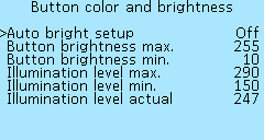 Auto bright setup — Off (Disabled) and On (Enabled). Select On to enable.
Button brightness max. — maximum brightness of buttons, values from 0 to 255, in 1 increments.
Button brightness min. — minimum brightness of buttons, values from 0 to 255, in 1 increments.
Illumination level max. — maximum lighting level, values from 1 to 300, in 1 increments.
Illumination level min. — minimum lighting level, values from 1 to 300, in 1 increments.
Illumination level actual — current lighting level.
Screen backlight
In the menu item On-board computer > On-board computer settings > Screen backlight, you can adjust the brightness of the backlight of the On-board computer screen.
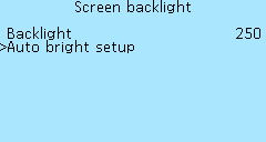 Backlight — backlight brightness, values from 0 to 255, in 1 increments.
If desired, you can enable automatic screen brightness adjustment using the light sensor in the menu On-board computer > On-board computer settings > Screen backlight > Auto bright setup.
 Auto bright setup — Off (Disabled) and On (Enabled). Select On to enable.
Backlight max. — maximum screen brightness in good lighting conditions, values from 0 to 255, in 1 increments.
Backlight min. — minimum screen brightness, in low light, values from 0 to 255, in 1 increments.
Illumination level max. — value from the light sensor at which the maximum brightness is considered, values from 1 to 300, in 1 increments.
Illumination level min. — value from the light sensor at which the minimum brightness is considered, values from 1 to 300, in 1 increments.
Illumination level actual — shows the current value from the light sensor.
We recommend that you first adjust the min/max light level by closing the light sensor with your finger. Then you can adjust the brightness of the backlight. Optimal values for night/day brightness are 30/255. The light sensor must be configured individually because a wide range of readings is possible.
Screen contrast setup
Menu item On-board computer > On-board computer settings > Contrast. Selecting the contrast level of the On-board computer screen, values from 30 to 100, in 1 increments. After setting the contrast level, save the settings in the On-board computer > Save menu.
Display heating
In the menu section On-board computer > On-board computer settings > LCD heater, you can turn on the screen heating of the On-board computer. This function is used to correctly display information on the screen in cold weather or when the screen fogs up. Consumption approximately 6W. Heating works automatically, when the specified temperature is reached, the heating is turned off, when the temperature drops, it turns on again.
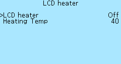 LCD heater — selecting Off (Disabled) and On (Enabled).
Heating Temp — selection of temperature values in degrees Celsius (°C) from 0°C to 60°C, in 1°C increments.
Main screen setup
In the menu section On-board computer > Main screen setup, you can configure the interface of the main screen of the On-board computer.
Information lines
In the menu On-board computer > Main screen setup > Information lines, information lines on the main screen are configured, the readings of which are toggled with the two central buttons, to the right and left. You can configure up to five lines. One or two parameters can be displayed simultaneously. All lines are configured identically. After making changes, go to the On-board computer > Save and save settings.
#Line 1 — #Line 5. Selecting a line number, if you specify only one parameter for a line, then only one value will be shown on the main screen.
Left var. — variable on the left side of the line.
Right var. — variable on the right side of the line.

List of parameters available for display:
Nothing — parameter is not displayed.
Voltage — battery voltage, Volts (V).
Current — battery current, Amperes (A).
Phase current — phase current, Amperes (A).
Watts — electric motor power, Watts (W).
Unused Wh — remaining battery capacity, Watt-hours (Wh).
Used Wh trip — energy consumption per trip, Watt-hours (Wh).
Used Wh total — energy consumption of all time, Watt-hours (Wh).
Used Wh user — energy consumption per user period of time (reset at will), Watt-hours (Wh).
Used Wh from chrg — energy consumption since charging, Watt-hours (Wh).
Unused % — remaining battery charge in percent, (%)
Wh/km trip — energy consumption per kilometer per trip, Watt-hours per kilometer (Wh/km) or Watt-hours per miles (Wh/mi) if you set up a Speed unit in mph.
Wh/km total — energy consumption per kilometer of all time, Watt-hours per kilometer (Wh/km) or Watt-hours per miles (Wh/mi).
Wh/km total user — energy consumption for a user-defined period of time per kilometer (reset at will), Watt-hours per kilometer (Wh/km) or Watt-hours per miles (Wh/mi).
Wh/km from chrg — energy consumption per kilometer since charging, Watt-hours per kilometer (Wh/km) or Watt-hours per miles (Wh/mi).
Mileage trip — mileage per trip, Kilometers (km) or Miles (mi).
Mileage total — mileage of all time, Kilometers (km) or Miles (mi).
Mileage user — mileage for a user-defined period of time (reset at will), Kilometers (km) or Miles (mi).
Mileage from chrg — mileage since charging, Kilometers (km) or Miles (mi).
Driving range trip — driving range per trip, Kilometers (km) or Miles (mi).
Driving range tota — driving range of all time, Kilometers (km) or Miles (mi).
Driving range user — driving range for a user-defined period of time (reset at will), Kilometers (km) or Miles (mi).
Driving range from chrg — driving range since charging, Kilometers (km) or Miles (mi).
Mid Speed trip — average speed per trip, Kilometers per hour (km/h) or Miles per hour (mph).
Mid Speed total — average speed of all time, Kilometers per hour (km/h) or Miles per hour (mph).
Mid Speed user — average speed for a user-defined period of time (reset at will), Kilometers per hour (km/h) or Miles per hour (mph).
Mid Speed from chrg — average speed since charging, Kilometers per hour (km/h) or Miles per hour (mph).
Motor t°C — motor temperature, degrees Celsius (°C).
Controller t°C — controller temperature, degrees Celsius (°C).
Motor RPM — motor revolutions per minute (RPM)
In the menu On-board computer > Main screen setup > Information lines > Cycling you can set up automatic scrolling of information lines on the main screen in the specified range.
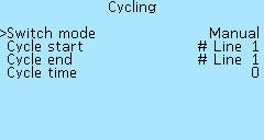 You can choose one of the following Switch mode for switching information lines:
Manual — without automatic scrolling, manual switching using the buttons on the On-board computer.
Auto range — automatic scrolling in the range of lines.
All auto — automatic scrolling of all information lines.
Cycle start — from which line will scroll, values from # Line 1 to # Line 5.
Cycle end — to which line will scroll, values from # Line 1 to # Line 5.
Cycle time — time period of automatic scrolling of all values in seconds, values from 1 sec to 255 sec, in 1-sec increments.
In the menu On board computer > Main screen setup > Information lines > Message you can enable or disable pop-up messages by their priority. This functionality has not yet been implemented.

Temperature graphs
For temperature graphs, you can configure the display limits, through the parameters in the section On-board computer > Main screen setup > Bar graph settings. If several controllers are connected, the highest temperature of the motor or controller will be displayed. After making changes, you must go to the On-board computer > Save and save settings.
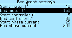 Start motor t° — minimum displayed motor temperature in degrees Celsius (°C), values from 5°C to 250°C, in 5°C increments.
End motor t° — maximum displayed motor temperature in degrees Celsius (°C), values from 5°C to 250°C, in 5°C increments.
Start controller t° — minimum displayed controller temperature in degrees Celsius (°C), values from 5°C to 250°C, in 5°C increments.
End controller t° — maximum displayed controller temperature in degrees Celsius (°C), values from 5°C to 250°C, in 5°C increments.
Start phase current — minimum displayed current in Amps (A), selectable from 5A to 500A, in 5A increments.
End phase current — maximum displayed current in Amps (A), selectable from 5A to 500A, in 5A increments.
Units of measure
In the menu On-board computer > Main screen setup you can select units for speed and temperature. After making changes, you must go to the On-board computer > Save and save settings.
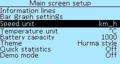
Speed unit — in kilometers per hour (km_h) or in miles per hour (mph).
Temperature unit — in degrees Celsius (°C) or degrees Fahrenheit (°F).
Battery capacity
In the menu On-board computer > Main screen setup > Battery capacity configures the display of the battery capacity on the Main screen. After making changes, you must go to the On-board computer > Save and save settings.
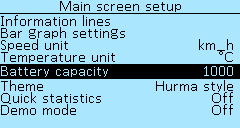
Battery capacity — the energy stored by the battery, in Watt-hours (W*h), the values from 5 W*h to 10000 W*h, with increments of 5 W*h.
Main screen theme
In the menu On-board computer > Main screen setup > Theme, you can choose a theme for the main screen interface. At the moment, there are three themes available, suggested by users — VasiliSk, Vitz, Hurma. After choosing a theme, you must go to the On-board computer > Save and save settings.
VasiliSk

Vitz

Hurma

Quick statistics
Menu item On-board computer > Main screen setup > Quick statistics. Quick statistics are displayed on the main screen instead of the speedometer when the speed is zero. By default, quick statistics is disabled (Off).
 You can choose to display several types of statistics: General, User, Trip, From charge. For a detailed description, see the Statistics section. The main screen displays five parameters:
Mileage — mileage in kilometers (km) or in miles (mi).
Max speed — maximum speed, in kilometers per hour (km/h) or in miles per hour (mph).
Avg speed — average speed, in kilometers per hour (km/h) or in miles per hour (mph).
Used Wh — energy consumption per trip, Watt-hours (Wh).
Wh\km — energy consumption per kilometer per trip, Watt-hours per kilometer (Wh/km).
In the future, will be able to function of change the list of displayed parameters.
After enabling the display of quick statistics, you must go to the On-board computer > Save and save settings.
Main screen animation
In the menu On-board computer > Main screen setup > Demo mode you can turn on the animation of the status bars on the main screen when starting the On-board computer. Select values On and Off.
Buttons setup
Menu On-board computer > Buttons setup menu allows you to configure the functions of the On-board computer buttons or external control buttons, switches, ignition key connected to the On-board computer. See the diagram in the Connection section.
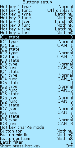 Menu items Hot key 1 — Hot key 4 — four buttons of the On-board computer, from left to right, are configured in the same way. The function assigned to them is activated by pressing and holding the button for 2 seconds. After setting, you need to save the parameters in the menu section Onboard computer > Save.
In the items Hotkey 1 type — Hotkey 4 type you can select the type of control signal that goes to the Controller. Value options:
None — turned off.
Latching — select, if necessary, that the Controller, when pressing and releasing the button, receives the “on” signal. When pressed and released again - signal “off”.
Normal — select, if necessary, that the Controller, when the toggle switch is turned on, receives the “on” signal, when the toggle switch is turned off, the “off” signal. For example, if you want to switch on one of the speed modes on the Controller with a button from the On-board computer. Also, the value Normal must be selected if you connect the brake levers with normally open contacts (NO).
Inverted — inverted switch state. This value must be selected when connecting brake levers with normally closed contacts (NC).
In menu items Hot key 1 func. — Hot key 4 func. selects the function assigned to the On-Board Computer button.
Nothing — function turned off.
USB Charger — the function of turning on and off USB charging by pressing and holding the On-board computer button. You can also enable charging forcibly in the Settings menu. See USB Charging Setup section above.
Security block — enabling a password during charging, so that you cannot change any settings while the battery is charging through the motor.
Turn off screen backlight — turn off the screen backlight with one button, for example, when charging.
CAN_1 — CAN_16 — selection of the CAN-input number when controlling via the CAN-bus. These are software values, there are fewer physical inputs on the boards, at the moment there are eight CAN-ports IO1-IO8 available in the On-board computer (see diagram).
Menu items IO1 — IO8 — numbers of inputs IO1-IO8 in the On-board computer. On the back of the On-board computer there is a panel with connectors, where you can connect control buttons and customize their functions. All inputs are configured in the same way. See section Connection. To see which input number the button has, go to the On-board computer > Information menu, press the button, and see for which input number the value 0 changes to 1. See the Information section.
In menu items IO1 — IO8 you can select the type of control signal, which is sent to the controller from the inputs IO1-IO8, respectively. The options for choosing values are similar to the Hotkey 1 type setting — None, Latching, Normal, Inverted.
In the menu items Input 1 func. — Input 8 func. selects the function assigned to the button connected to the On-Board computer. The value selection options are similar to Hotkey 1 type — Nothing, USB Charger, Security block, Turn off screen backlight, CAN_1-CAN_16.
The Hot key charge mode menu item allows you to customize the functionality of the On-board computer buttons in charging mode, which allows you to use the same button to activate different functions while driving and while charging. The settings are similar to the Hotkey 1 type-Hotkey 4 type menu items and Hotkey 1 func.-Hotkey 4 func..
Button top, Button middle, Button bottom — setting the functions of a three-button control panel. The connection diagram will be available later. The options for selecting values are similar to the setting Hot key 1 type — Nothing, USB Charger, Security block, Turn off screen backlight, CAN_1-CAN_16.
In the menu item On-board computer > Button setup > Latch filter, you can configure a filter for more stable button operation. The choice of values from 0 to 10. This setting refers to the four buttons of the On-board computer Hotkey 1-Hotkey 4. Sometimes, especially if the functions are configured for all four buttons, interference may occur that will affect the stability of the buttons. In this case, you can increase the filter value. The button will turn on more slowly (it will need to be held longer), but more stable.
The Onboard computer > Button setup > Short press hot key menu item allows you to configure the activation of the function by short pressing the On-board computer buttons, without holding it for 2 seconds.
Control setup
In the menu section On-board computer > Control setup, the parameters of the throttle and brake levers connected directly to the Onboard computer are configured. If the throttle and brake levers are connected to the Controller via control-side inputs, their settings must be done in the Controller > Control menu section.
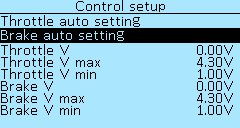 Throttle auto setting — automatic throttle range setup mode. To start the mode, press the right button of the On-board computer and follow the instructions on the screen.
Brake auto setting — automatic brake range setup mode. To start the mode, press the right button of the On-board computer and follow the instructions on the screen.
ThrottleV — current voltage of the throttle grip connected to the On-board computer, in volts (V).
Throttle V max and Throttle V min — the range of the throttle grip, in volts (V), selection of values from 0.01V to 5.00V, in increments of 0.01V. If the maximum value is exceeded by 5%, protection against a broken throttle grip will be activated. If your range is incorrectly set, then when you fully press the throttle handle, the electric motor will turn off, in this case you need to increase the range value.
BrakeV — current voltage of the brake lever connected to the on-board computer, in volts (V).
Brake V max and Brake V min — range of the brake lever, in volts (V), selection of values from 0.01V to 5.00V, in increments of 0.01V.
Data sources setup
In the menu section Onboard computer > Data sources are configured data sources for various indicators of the Onboard computer.
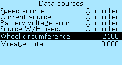 Speed source — selection of speed data source Controller or Display.
Current source — selection of the current source data Controller or BMS.
Battery voltage source — selection of the battery voltage data source Controller or BMS.
Source W/H used. — select the source of the battery power consumption data Controller or BMS.
Wheel circumference — wheel circumference in millimeters, values from 100 to 3000, in 1 increments. This setting is used when selecting an external sensor connected to the On-board computer as a speed source.
Mileage total — controller's mileage in kilometers (km).
The On-board computer supports two ways to determine the speed:
— according to information from the Controller.
— by a speed sensor (reed switch), which is connected to the On-board computer.
If you select the Controller value, the controller readings will be used as the speed data source. This method is suitable for direct-drive or mid-drive motors without overrunning clutch. After selecting the value Controller, you must:
1. Specify the number of pole pairs for the magnets in the menu Controller > Motor setup > Pole pair. The number of pole pairs for different models of motors can be found in the Motor Information section. If your motor is not on the list, check with the manufacturer or use an Internet search.
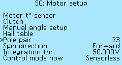
2. Enable speed calculation (if disabled) in the Controller > Extra parameters > Speed calculation and specify the wheel circumference in millimeters in the Controller > Extra parameters > Circumference. You can use the online calculator to calculate the circumference.

If selecting a value Display the speed will be determined from an external sensor, which is used, for example, in a bicycle computer. The speed sensor must be connected according to the diagram to the SPEED connector on the rear panel of the On-board computer. After setting the Display value and connecting the speed sensor, you must specify the wheel circumference in millimeters in the On-board computer > Data source menu.
Security and password setup
In the menu section On-board computer > Security you can set a password that will be requested when turning on the Controller. Without entering the password, the controller will not respond to controls.
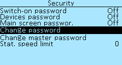 Switch-on password — enabling the password request when starting the controller. Select Off and On. The password is set under Change password — changing the default password. To set your password, go to Change password, you will be prompted to enter your password. Enter the default password 1234 by pressing the On-board computer buttons from left to right. Enter a new password, you can assign up to 10 keystrokes. For example, 10 clicks on button 1 or 5 clicks on button 2 and 5 on button 3. After entering the new password, press and hold the right button. Re-enter the new password. Save the settings in the menu On-board computer > Save to save the new password.
Attention! There is no way to recover a forgotten password on your own. Later, the function of recovering the password by the controller serial number will be added.
Device password — enable the password request to enter the settings of any device connected via the CAN bus and visible in the menu Settings > Devices. Select Off, Once or Permanently. If you select Once, the password will be requested only once when you try to enter the device menu after turning on the controller. If you select Permanently, the password will be requested each time you try to enter the device menu after turning on the controller. To set a password, use the Change master password menu item.
Main screen password — enable the password request when trying to enter the On-board computer menu from the main screen. Select Off, Once or Permanently. If you select Once, the password will be requested once when you try to enter the screen menu after turning on the On-board computer. If you select Permanently, the password will be requested each time you try to enter the screen menu after turning on the On-board computer. To set a password, use the Change master password menu item.
Change master password — sets the master password that is used to set the Device password and Main screen password. The same password is used for both settings. To set your password, go to Change master password, you will be prompted to enter your password. Enter the default password 1234 by pressing the On-board computer buttons from left to right. Enter a new password, you can assign up to 10 keystrokes. For example, 10 clicks on button 1 or 5 clicks on button 2 and 5 on button 3. After entering the new password, press and hold the right button. Re-enter the new password. Save the settings in the menu On-board computer > Save to save the new password.
Stat. speed limit — limiting the maximum speed value that will be displayed in the On-board computer statistics. Values from 1 to 255, in increments of 1.
Firmware update
In the menu item On-board computer > Update and settings > Firmware update you can update the firmware of the On-board computer. You can download the latest firmware version in the Firmware section.
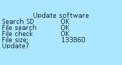 To update, download the firmware file to the root directory of the microSD card with Fat/Fat32 file system. Insert the card, with the contacts on top, into the connector on the On-board Computer. This can be done without turning off the On-board computer, but in this case, you must exit the Firmware update menu and re-enter. After that, the On-board computer will detect the microSD card, display the File size in bytes and the menu item Update? Press the right button of the On-board computer to start the update. After restarting, check the firmware version under On-board Computer > Device Information.
In the menu item On-board computer > Update and settings > Forced update of devices you can force a firmware update of any device visible in the Setting > Devices menu without having to go to the menu of each device separately to update it. This function will also be useful if you have updated the On-board computer to the latest firmware, and the Controller has firmware v.7.18 (and lower) and is not visible in the Setting > Devices menu due to the new protocol.
To update, download the firmware file to the root directory of the microSD card with Fat/Fat32 file system. Insert the card, with the contacts on top, into the connector on the On-board Computer. After that, go to the menu item On-board computer > Update and settings > Forced update of devices and select the device you want to update. Press the right button on On-board Computer to start the update. After restarting, check the firmware version under On-board Computer > Device Information.
Reset settings
In the menu section On-board computer > Update and settings > Reset settings, you can reset all settings to the factory settings. To reset, press the right button of the On-board computer.
Import and export of settings
In the menu items On-board computer > Update and settings > Export parameters and On-board computer > Update and settings > Import parameters you can export and import previously made On-board computer settings to the microSD card.
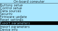 Export parameters — insert the microSD card into the slot of the On-board computer and press the right button. A file will be created on the microSD card with the name NDconf0.cfg — NDconf9.cfg, up to a maximum of 9 different configurations. You can open the created file with the “Notepad” program, see all your settings, make any changes, save. Likewise, you can import a previously saved configuration into the On-board computer.
Import parameters — import of On-board computer settings configuration from microSD card, file name for import only NDconf0.cfg! Click on the right button to import. When importing, a message will be displayed with the number of possible errors, found and accepted parameters.
Device information
In the menu section On-board computer > Device info, you can view basic data on the On-board computer. In this menu you can check what version of the firmware is loaded into your On-board computer.
 Nucular Display — device name.
HW version — hardware version.
HW data — date of hardware production.
SW version — firmware version, you can download the latest firmware in the Firmware section.
SW data — firmware compilation date.
Memory
In the menu section On-board computer > Update and settings are the menu items for working with memory of the On-board computer.
Save dump — copying information about the state of the system (memory dump) to an SD card. This function is used by developers to find errors in the device code.
Erage storage — erase the memory and all settings of the On-board computer.