meta data for this page
uLight (v.0.6.3)
The uLight is a controller designed to control lighting equipment, such as turn signals, brake lights, headlights, or LED strips. The uLight board has three CAN inputs and can function as a CAN splitter. Video review on YouTube. The uLight does not have its own power supply.
Technical specifications:
- Size 55x30x13 mm, weight 25 g
- Input 10-15V
- The current of one channel 3A, 6 outputs
- Total current ~ 10A (with external supply)
- 6 digital inputs
- 2 thermosensor inputs
- 2 digital outputs
- 3 CAN bus connectors
In the kit:
- uLight controller — 1 pcs.
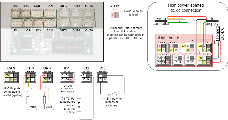
- PHD 2.0 4P connector — 4 pcs.
- PHD 2.0 6P connector — 4 pcs.
- Power wires 22AWG 2×200 mm with connectors XH 2.54 2P — 6 pcs.
- Power wires 22AWG 300 mm with pins, crimped on both sides — 8 pcs.
- Wires 26AWG 300 mm with pins, crimped on both sides — 20 pcs.
Connection
You can look at the connection diagrams for other devices at this link.
Connecting uLight to the Controller and the On-Board computer is possible in different ways:
- By CAN-wire, which is purchased separately (not included in the kit). In this case, the standard CAN-wire from the Controller is connected to one of the CAN-ports on the uLight board, and the second CAN-wire from the uLight is connected to the On-board computer.
- By standard CAN-wire between the On-board computer and the Controller. In this case, the CAN wire must be cut and crimped with two PHD 2.0 6P connectors (included in the kit).
- By CAN wire through a CAN splitter, if it is used in your connection scheme, as a rule, such a scheme is used in all-wheel drive scooters with two controllers. In this case, it is better to connect the On-board computer directly to uLight, which is connected via a CAN wire to a CAN splitter, to which the Controllers are connected.
If necessary, you can connect all peripherals to the uLight board to control the Controller (throttle levers, brakes, switch buttons) via the CAN bus without using the On-Board Computer. But, setting up the uLight and the Controller is possible only from the On-Board Computer. When all devices have been configured, the On-board computer can be disconnected.
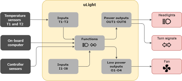
The logic diagram
Setup
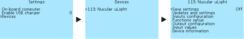
The uLight setup menu is located under Settings > Devices > Nucular uLight. Below you can find a detailed description of the menu items.
Save settings
Saving all settings made. Select On to save. If you do not save the settings, they will be reset after restarting of uLight.
Firmware updates
Section for working with firmware updates and settings.
 Reboot — some parameter settings, such as PWM and frequency, will be applied only after a reboot.
Load defaults — reset all settings made.
Update firmware — when you select On, the uLight firmware update will start, provided that an SD card with the firmware file is inserted into the On-board computer. You can download the current firmware version and read the update instructions in the Firmware section.
Inputs configuration
The functions of inputs I1-I6 (see diagram above) are selected in the Function setup section. Two thermal sensors can be connected to uLight.
 T-sensor T1 type — selection of NTC10K3950 or NTC10K3380 thermal sensor. Select Off if no sensor is connected.
# T-sensor T1 — current temperature of the thermal sensor Т1 in degrees Celsius (°C).
T1 Threshold (port I7) — I7 is a virtual port intended to function setup (see Function setup). Values from 0°C to 250°C, in 1°C increments.
Т1 Threshold mode — signal operation mode from the thermal sensor, selection of values Normal (the signal state is first “off” when triggered is “on”) and Inverted (the signal state is first “on”, when triggered is “off”).
The settings for Temperature sensor T2 are similar to those for Temperature sensor T1.
CAN-Control — this setting refers to the THR (throttle), BRK (brakes), IO2, and IO3 inputs on the uLight board and is used when the throttle, brakes and switches are connected directly to the uLight board. When you select the On setting, control signals from the inputs will be transmitted via the CAN bus and you will be able to control the Controller from the uLight board using the throttle, brake and switch inputs.
CAN ports — redirecting inputs to groups of CAN ports for controlling the controller. Selectable values — OFF, CAN 1-8 and CAN 9-16.
Function setup
Function setup allows you to select which function each input on the uLight board or CAN input in the Controller or On-board computer corresponds to. All settings in this section of the menu have the same selection of functions:
Off — disabled.
On — enabled. If the lights are connected, they will light constantly.
I1-I6 — select the number of the input on the uLight board to which the switchch for turning on the lights is connected. You can check the operation of the button in the menu section Inputs values, items Input I1-Input I6, when the button is turned on, the values will change to On.
I7_T1 and I8_T2 — selection of the virtual port of the temperature sensor T1 and T2.
C1-C16 — selection of the CAN input number when controlling via the CAN bus. It is used when connecting external control buttons to the On-board computer or when using the On-board computer buttons (Hot key). C1-C16 are software values, there are fewer physical inputs on the boards, currently, eight CAN ports IO1-IO8 are available on the On-board computer (see diagram).
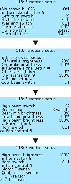
Shutdown by CAN — this setting allows you to turn off all lighting equipment if you turned off the Controller but didn't turn off the power supply to the uLight board. The shutdown signal will be transmitted via the CAN bus and all lighting equipment will be turned off. The default is Off (Disabled). This setting is used if the uLight board has a separate power supply from an external direct current (DC) source. With the setting On (Enabled), the lighting equipment will continue to work when you turn off the power of the Controller and the On-Board Computer. If the uLight board receives power via the CAN bus and the On value is selected, uLight will turn off the power if it does not receive a CAN bus signal from any of the devices (Controller or On-board computer).
# Turn signals setup #
Settings for the left and right turn signals. Read more about the setup below in the section Turn signals setup.
Left turn switch — setting for the left turn signal button.
Right turn switch — setting for the left turn signal button.
Warning switch — setting for the hazard warning light switch.
Turn brightness — select the brightness of the turn signals from 0% to 100% in 5% steps.
Time on-time — the speed of turning on the turn signals, together with setting the off time, allows you to control the speed of blinking of the turn signals. Values from 0.1 sec to 1 sec, in 0.1-sec increments.
Turn off-time — turn off speed. Values from 0.0 sec to 1 sec, in 0.1-sec increments. Setting the value to 0.0 sec will disable the blinking function of the turn signals.
# Brake signal setup #
The brake signal is adjustable in two brightness levels.
Off-brake brightness — the brightness of the brake light when the brake is not pressed, for use as taillights, a value from 0% to 100% in 5% increments.
On-brake brightness — the brightness of the brake light when the brake is pressed, a value from 0% to 100% in 5% increments.
# Reverse signal setup #
Adjust the brightness of the light of reverse. The uLight board does not have an input for the switch of reverse, therefore, this function is controlled from a switch connected to the On-board computer or Controller. When the Controller is turn on reverse, the signal on the uLight board will also be active.
Off-revers bright. — the brightness of the reversing light without engaging reverse, a value from 0% to 100% in 5% increments.
On-revers bright. — the brightness of the reversing light when reverse is engaged, a value from 0% to 100% in 5% increments.
# Beam setup #
Low beam switch — the select setting for the low beam switch.
High beam switch — the select setting for the high beam switch.
Beam mode — this setting is selected depending on how the headlight is connected with one or two wires. Single — it is used if one headlamp performs the functions of low and high beam and is connected with one wire to one of the power outputs on the uLight board, for example, OUT1. Separate — if two different headlights are used for low and high beam, or when one headlight is used, which has two lamps inside and is connected with two wires to two power outputs on the Microlight board, for example, OUT1 and OUT2.
Beam min brightness — the brightness of the headlight when the power button is deactivated, for example for use as daytime running lights. Value from 0% to 100% in 5% increments. When using a headlamp with a converter, the minimum brightness must be set to either 0% or 100%, the headlamp will flicker at intermediate values.
Low beam brightness — select the brightness of the low beam, values from 0% to 100% in 5% increments.
High beam brightness — select the brightness of the high beam, values from 0% to 100% in 5% increments.
# Horn setup #
A horn can be connected to the uLight board, if necessary.
Horn switch — the select setting for horn switch.
# Fan control #
Fan control allows you to adjust the cooling of the motor or Controller or using other scenarios using temperature sensors. Two temperature sensors can be connected to the uLight board. The setup menus for all temperature sensors are the same.
Motor T-sensor — motor temperature sensor.
Controller T-sensor — temperature sensor of the controller.
Т1 Т-sensor — external temperature sensor Т1.
Т2 Т-sensor — external temperature sensor Т2.
The setup menus for all temperature sensors are the same. Below is a description of the menu using the example of a T1 T-sensor.

Temperature min — minimum temperature, values from -30 °C to 125 °C, in 5 °C increments.
Temperature max — maximum temperature, values from -30 °C to 125 °C, in 5 °C increments.
Output min — minimum output (PWM), values from 0% to 100%, in 5% increments.
Output max — maximum output (PWM), values from 0% to 100%, in 5% increments.
Output configuration
In this section, you can configure which output each function belongs to. The uLight has six power outputs OUT1-OUT6 (see the diagram above). All outputs are PWM frequency adjustable.
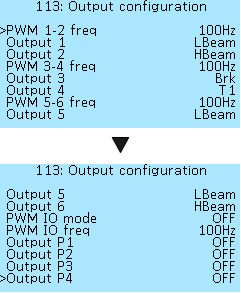 PWM 1-2 freq — a setting for advanced users. Selectable PWM frequency values — 100Hz, 500Hz, 1kHz, 5kHz, 10kHz, 24kHz (FAN). For the usual light bulb, large values are not needed. Select a frequency of 100Hz, this will be enough not to see flicker. The high-frequency marked FAN is used to control the fans, this is their standard frequency.
Output 1 — setting the function of output 1 (OUT1) of the uLight board. Selectable values — OFF (Disabled), ON (Always on), Bttn (Button, not yet implemented), TurnL (Left turn signal), TurnR (Right turn signal), Brk (Brake), LBeam (Low beam), HBeam (High beam), Rev (Reverse), Horn, TMot (Motor temperature), TCont (Controller temperature), T1 (External temperature sensor T1), T2 (External temperature sensor T2).
Output 2 — the setting is similar to Output 1.
The frequency of PWM 3-4 and PWM 5-6 and their outputs Output 3-6 are configured in the same way.
There is an IO1 port on the uLight, in which there are four low-power PWM outputs O1-O4. They can connect, for example, an optocoupler. In the menu, you can select the mode of operation of the PWM at the outputs, its frequency, and the value of the function for each output. Outputs O1 and O2, O3 and O4 can be connected in parallel to increase the total current.
PWM IO mode — is a setting for advanced users. Selecting the PWM mode of the IO outputs — OFF, Open-drain, Push-Pull.
PWM IO freq — is a setting for advanced users. Selecting the frequency values of the PWM IO outputs — 100Hz, 500Hz, 1kHz, 5kHz, 10kHz, 24kHz (FAN).
Output P1 — setting the function of the PWM output of the low power IO1 of the uLight. Selectable values — OFF (Disabled), ON (Enabled), Bttn (Button, not yet implemented), TurnL (Left turn signal), TurnR (Right turn signal), Brk (Brake), LBeam (Low beam), HBeam (High beam), Rev (Reverse), Horn, TMot (Motor temperature), TCont (Controller temperature), T1 (External temperature sensor T1), T2 (External temperature sensor T2).
Outputs P3-P4 are configured in the same way as Output P1.
Input values
In this section of the menu you can see the values of the indicators at each input of the uLight board. This menu is similar to the Debug information item in the Controller menu.
 Current — current consumption of headlights, Amperes (A).
Voltage — supply voltage of the uLight board, Volts (V).
Throttle — voltage on the throttle levers connected to the Microlight board, Volts (V).
Brake — voltage on the throttle levers connected to the uLight board, Volts (V).
T-sensor internal — the temperature at the uLight board temperature sensor, degrees Celsius (°C).
T-sensor T1 — temperature at the external temperature sensor T1 connected to the uLight board, degrees Celsius (°C).
T-sensor T2 — temperature at the external temperature sensor T1 connected to the uLight board, degrees Celsius (°C).
Input I1-Input I6 — values of buttons or switches connected to the uLight board, Off or On. When you turn on the button or switch connected to the uLight board, the values will change from Off to On, this functionality allows you to check the operation of the buttons and to which board inputs they were connected.
Device information
Basic information about the uLight controller. In this menu, you can see what version of the firmware is loaded into your uLight controller.
 Nucular uLight — is the name of the device.
Firmware date — date of compilation of the firmware.
Firmware ver — firmware version, you can check for updates in the Firmware section.
Loader date — date of compilation of the loader.
Loader version — the version of the data loader.
Power cycle — the number of uLight board power-ups.
Power-on time — the operating time of your uLight, minutes, hours, days.
Settings examples
Connecting and set up the headlight
In this example, we will look at the connection and setup of the headlight. To control the headlamp, we will use a three-wire, three-position switch. Turn signals and brake light are set up in the same way. Depending on the way the headlight is controlled, you can choose several settings:
- control from external buttons of the switch connected to the uLight board.
- control from external buttons of the switch connected to the On-board computer.
- control from the buttons on the On-board computer.
Supply connection
Connect the headlamp according to the diagram (see above) to one of the OUT1-OUT6 power outputs on the uLight board. Maximum current per channel 3A, total no more than 10A, which are available only when using an external DC converter. To connect, use the supplied uLight power wires 22AWG 2×200 mm with connectors XH 2.54 2P. Solder them to the headlight wires, “+” and “-” respectively. If four wires are used to connect the headlight, then you can connect them to the power outputs of the uLight board in parallel vertically, OUT1-OUT2, OUT3-OUT4, OUT5-OUT6.
Control from external buttons of the switch connected to the uLight board
After connecting the headlight power supply, need to connect an external switch to the uLight board to control the headlight. For connection according to the diagram (see above) use inputs I3-I4 of port IO2 or I5-I6 of port IO3.
 You can check the operation of the connected switch in the Inputs values menu section, when you turn the switch buttons on and off, the value of one of the inputs I1-I6 to which you connected the switch will change from Off to On. You can also use this menu to see what input number the connected switch has before the output configuration setup. In the example on the screenshot the left, we see that one of the switch buttons is connected to Input I5, the second button will change the value of Input I6. Next, you need to configure the outputs and their functions in the menu of the uLight board. The order of settings does not matter, the main thing is that the output corresponds to the function and vice versa.
Function setup
You need to go to the Function setup menu and then, go to the Beam setup section.
 Next, select which output the low beam switch is connected to, for example, you connected a switch button to Output I3. Next, select which output the high beam switch is connected to, for example, to Output I4. It is impossible to assign the inclusion of low and high beam to one button, only to a switch or to two separate buttons. For a description of the Single and Separate beam modes, see above in the Beam setup menu section.
Output setup
Go to the Outputs configuration menu, select the numbers of the OUT1-OUT6 outputs to which the headlight is connected and assign them a function. For example, you connected a headlight with two pairs of wires to the OUT1 and OUT2 outputs.
 Taking into account the previously made settings for the functions, go to Output 1 and select the value LBeam (Low beam). Next, go to Output 2 and select the HBeam (High beam) value. You can leave the PWM frequency for a regular bulb at 100Hz.
Then return to the main menu, go to the Save settings item and select On to save the settings. Done. Check the operation of the headlight in the low and high beam mode by turning on the switch buttons.
Control from external buttons of the switch connected to the On-board computer
After connecting the power supply for the headlight power supply, need to connect an external headlight control switch to the On-board computer. For connection according to the diagram, use the inputs IO1-IO3 of the I/O1 port or IO4-IO6 of the I/O2 port located on the rear side of the On-board computer.
 You can check the operation of the connected switch in the On-board computer > Information menu section, when you turn on and off the switch buttons, the value of one of the inputs Input 1 func-Input 8 func to which you connected the button will change from 0 to 1. You can also use this menu to see what input number the connected switch button has before the stage of setting the outputs. In the screenshot on the left, the switch is connected to the On-board computer to the I/O2 port and one of its buttons to the IO2 input. Next, you need to configure the inputs in the On-board computer and their functions in uLight. The order of settings does not matter, the main thing is that the output corresponds to the function and vice versa.
Setup inputs in the On-board computer
Need to go to the On-board computer menu and go to the Button setup menu section.
 Next, need to select which input the Low beam button is connected to, for example, you connected the button to the Input 2 input as in the example above. Go to the menu item Input 2 func and configure the function of the button, CAN button 2. Next, select the type of switch Switch in the menu item Input 2 type.
Next, select which input the High beam button on the switch is connected to, for example, to Input 3. Go to the Input 3 func menu section. and configure the function of the CAN button 3. Next, select the type of button Switch in the menu item Input 3 type.
After all the settings, go to the Save settings menu item and save the settings. This completes the setting of the switch connected to the On-board computer. Next, you need to configure the outputs and their functions in the menu of the uLight board. The order of settings does not matter, the main thing is that the output corresponds to the function and vice versa.
Setup functions in the uLight
You need to go to the Function setup menu and go to the Beam setup menu section.
 Next, we select which input the Low beam button is connected to in the On-board computer, previously we connected the button to the Input2 input and assigned the CAN button2 function, which means we select the C2 value. Next, select which input the High beam button is connected to, for example, to the Input3 input and you assigned the CAN button3 function, which means we select the C3 value. It is impossible to assign the inclusion of Low and high beam to one button, only to a switch or to two separate buttons.
Output setup
Go to the Output configuration menu, select the numbers of the OUT1-OUT6 outputs to which the headlight is connected and assign them a function.
 For example, you connected a headlight with two pairs of wires to the OUT1 and OUT2 outputs. Taking into account the previously made settings for the functions, go to the Output 1 section and select the LBeam (Low beam) value. Next, go to the Output 2 section and select the HBeam (High beam) value. You can setup the PWM frequency for a regular bulb at 100Hz.
Then return to the main menu, go to the Save settings section and select On to save the settings. Done. We check the operation of the low and high beam headlights by turning on the switch buttons.
Control from the buttons on the On-board computer
After connecting the headlight power supply, it is necessary to configure the On-board computer buttons. Go to the menu On-board computer > Buttons setup. All four front buttons of the On-board computer can be configured in the Hot key1-Hot key4 menu sections. Buttons activate functions when pressed and held while the Main screen is displayed.
 For example, you want to control the inclusion of the low beam with the first button on the screen. Go to the Hot key 1 type section, select the Button. Next, assign a function to the button in the Hot key 1 func, for example, CAN Button1. Similarly, we set up the second screen button to turn on the high beam on CAN Button2. After all the settings, go to the Save section menu and save the settings. This completes the configuration of the On-board computer buttons. Next, you need to configure the outputs and their functions in the menu of the uLight board. The order of settings does not matter, the main thing is that the output corresponds to the function and vice versa.
Setup functions in the uLight
You need to go to the Functions setup menu section and go to the Beam setup section.
 Next, select which button of the On-board computer the Low beam switch is connected to, we assigned the function CAN Button1 to the first button, need to select the value C1. Next, we select which button of the On-board computer the High beam switch is connected to, we assigned the function CAN Button2 to the second button, need to select the value C2. It is impossible to assign the inclusion of low and high beam to one button, only to two separate buttons.
Output setup
Go to the Outputs configuration menu section, select the numbers of the OUT1-OUT6 outputs to which the headlight is connected and assign them a function.
For example, you connected a headlight with two pairs of wires to the OUT1 and OUT2 outputs. Taking into account the previously made settings for the functions, go to the Output 1 section and select the LBeam (Low beam) value. Next, go to the Output 2 section and select the HBeam (High beam) value. You can set up the PWM frequency for a regular bulb at 100Hz.
Then return to the main menu, go to the Save settings section and select On to save the settings. Done. We check the operation of the low and high beam headlights by turning on the switch buttons.
Brake light setup
The setting is carried out in the same way as for connecting and setting up the headlight, except for the section Control from external buttons of the switch connected to the uLight board. Also read the description of the Brake signal setup menu section.
Reverse signal setup
Similar to connecting and setup the headlight. Also, read the description of the Reverse signal setup menu section.
Turn signal setup
Similar to connecting and setup the headlight. Also, read the description of the Turn signal setup menu section.
Horn setup
Similar to connecting and setup the headlight. Also, read the description of the Horn setup menu section.
Fan setup
Similar to connecting and setup the headlight. Also, read the description of the Fan control menu section. You can connect the fans directly to the controller through the P1/P2 inputs of the PWM port (optional, need to order PWM wire). Detailed description in the section Fan and Light Control.
Temperature sensors setup
Read the description of the Inputs configuration menu section. When the temperature sensors are connected to the uLight board, their temperature will not be displayed on the Main screen of the On-board computer, this functionality has not yet been released.
Throttle setup
Connect the throttle levers according to the diagram to the THR input on the uLight board. Next, go to the Input values menu section and check the operation of the throttle levers by switching it, the voltage value in the Throttle item should change. Next, go to the Input configuration menu section, then the CAN control section and select On. Next, you need to set up the voltage range of the throttle in the Controller.
Brake setup
Connect the brake levers according to the diagram to the BRK input on the uLight board. Next, go to the Input values menu section and check the operation of the brake levers by switching it, the voltage value in the Throttle item should change. Next, go to the Input configuration menu section, then the CAN control section and select On. Next, you need to set up the voltage range of the brake in the Controller.